
 United Kingdom (1918-1922) -Unbuilt.
WW1 RN Battleships
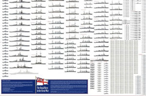
HMS Dreadnought | Bellerophon class | St. Vincent class | HMS Neptune | Colossus class | Orion class | King George V | Iron Duke class | HMS Agincourt | HMS Erin | HMS Canada | Queen Elizabeth class | Revenge class | G3 classMajestic class | Centurion class | Canopus class | Formidable class | London class | Duncan class | King Edward VII class | Swiftsure class | Lord Nelson class
Invincible class | Indefatigable class | Lion class | HMS Tiger | Courageous class | Renown class | Admiral class | N3 class
The first true British “hyper-dreadnoughts”
Comparison G3/N3
The term “super-dreadnought” was already coined when the Orion class was unveiled in 1909, armed with 13 in guns instead of 12 inches. In 1913 when was launched the first of the Queen Elisabeth class, the term received a new meaning, as not only the new class had 15 inches (381 mm), it was also way faster, at 24 nots instead of 21, earning the title of “fast battleship”. The Revenge class was a “battleship on a budget”. Smaller, slower, but armed the same and protected also the same, it was definitely not popular. The wartime experience and battle of Jutland redefined many pre-requisites for the next class, and somewhat showered the hopes of some with the Admiral class Battlecruiser to design a “universal capital ship”, reasonably fast (more than the previous Revenge) and heavily armed.
In 1916, the US Congress had been presuaded by the admiralty to built a navy “second to none”, with a large number of battleships and battlecruisers. The Japanese also in 1916 started a large programme called the 8-8 fleet while the British were converting two improved Revenge-class hulls as Renown-class battlecruisers. The only new capital ships during wartime laid down has been the Admiral-class battlecruisers. The Admiral class design was entirely revised after the Battle of Jutland in May 1916 and soon while the remainder three ships of the class were cancelled, Hood was completed much later.
The US battleship plan fell back to building smaller ships, such as destroyers and ten light cruisers, but intended to resume cosntruction of the Constitution class battlecruisers and South Dakota class battleships. Estimates by the Admiralty for the early 1920s meant the Royal Navy would fell behind for capital ships. Indeed in 1920-21, four new BS were completed, five more were in construction and seven more planned to be laid down in 1920–21. These South Dakota class with their twelve 16-inch guns also outclassed any Britsish capital ship and the Japanese had even more grandiose plans: One battleship has been completed since the end of the war, three more were under construction. The Admiralty initially planned to build three battleships for one battlecruiser for the year 1921–22 but this was changed to four G3-class battlecruisers and four battleships the next year.
The design lineage, U, L, and N (1920)
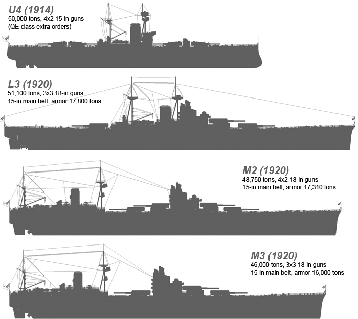
The U series were two extra orders for Canada, suggested by D.K. Brown of the Queen Elizabeth class ships, instead of “Improved Agincourts”. At the time, the Government tried to convince Canada to finance them. These evolved ot to be copy-paste designs but records are very sketchy. Nominal speed of 25kts, like QE but with a large single funnel. However U4 was a game changer, as it had all four turrets on the same level to solve the problem of early directing superfiring ones. U5 had the forward turrets en echelon. Main belt was sacrificed down to 12in, but for better deck armour. This study was suspended in 1915 as the “repeats” were converted as the Renown class battlecruisers instead at Fisher’s request.
By June 1920 two design derived from the “U-4” were prepared, 50,000 long tons (51,000 t), with eight to nine main guns in four twin or three triple configurations. They swapped to a bold new gun caliber: 18-inch (457 mm), under development in 1919. The problem of these large ships were too much for British dockyards of the time, or even pass through the Suez Canal. An additional problem is that these turrets were not in superfiring positions, to lower the centre of gravity and avoid the extra weight of the superfiring barbettes. This new generation could withstand 18in or 15in gunfire, and was supposed to be “universal” (blending both battlecruiser and battleship role).
These grand designs were however scaled down in October 1920, then split into separate battleship and battlecruiser designs: The two projects (battleship and battlecruiser) were numbered respectively from J upwards and J downwards. Battleship designs went thus from L through N, the associated number reflecting twin or triple turret variants.
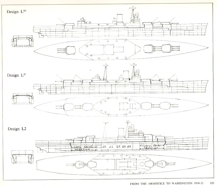
The ‘L2’ and ‘L3’ had superfiring guns, plus a 15-inch (381 mm) sloped waterline belt armor but also a 8 in armoured deck and 9 inches slopes. Both had were 25 knots (46 km/h; 29 mph) capable but the ggreat noverlty there was their transom stern and straight bow with no ram. Possibly D’Encourt himself suggested that the long standard stern was just “kissing the water” and was not going to miss if cut off square. By March 1920 already Naval Engineer Haslar tested models with transoms for the initial battlecruiser design and configuration cutoff 30ft, 15ft, 7ft 6in and right at the rudder were tested, with resistance curves identical. Loss of efficiency was noted however arund 15 kts. Superintendent S. Payne finalyzed the stern design, going for a broad transom for stability in damaged condition, still equivalent to a 20ft longer hull.
‘L2’ design was 52,100 long tons, 70,000shp, 25kts, 4×2 18in, 8×2 6in, 6×1 4.7in HA, 4×10 2pdr, two ASW TTs 24.5in, 15in thick main belt/25° over 470ft long, 18,850 tons of armor (37.1% of the displacement).
‘L3’ was lighter at 51,000 long tons, same powerplant, 3×3 18in, and same, same main belt but 445ft long and 17,800 tons of armour (36.3%).
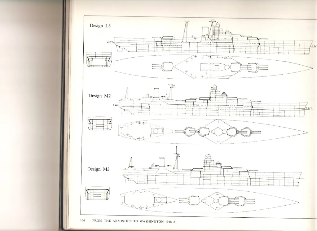
‘M2’ and ‘M3’ were were submitted later in 1920 with the aft turret(s) moved amidships to shorten the length of the armoured citadel. This saved 1,540 long tons/1,740 long tons of armour for with a reduced powerplant and top speed at 23–23.5 knots using two larger propeller shafts instead of four. On the first design, fire arcs were restricted to 60° off the bow/75° forward of the stern and blast effects were to be severe on the bridge.
‘M2’ design was 805 (wl) x 106 x 33ft, 48,750 tons, 56,000shp, 23kts, 4×2 18in, 8×2 6in, 5×1 4.7in HA, 4×10 2pdr, 2x 24.5in TTs, same 15in main belt/25° over. 440ft, deck 8-9in for 17,310 tons total.
‘M3’ design was 765 (wl) x same, 46,000 tons and same shp for 23.5kts, 3×3 18in and same. Same main belt mounted internally, 401ft, same deck armor, for 16,060 tons. This was an aft engine design, saving 1,500-1,800 tons of armour.
The lengthened version of the M3 design was eventually chosen by the admiralty. which was a basis for development leading to the N3, approved in November 1921.
The idea of saving weight by concentrating artillery in some place was further developed with the modified M3 and her forward artillery, behind the bridge and machinery spaces. The tower bridge structure behind the first two gun turrets was also a novelty. There was no longer a tripod, providing a more stable basis, vibration-free, for the fire-control station, and improved accommodation and protection. However the proximity of the main artillery was seen as a future problem.
Design in detail
The N3 battleships in the end, were much larger than the Revenge class at 820 feet (249.9 m), by 106 feet (32.3 m) in width and 33 feet (10.1 m) deeply loaded, displaced an estimated 48,500 long tons (49,300 t) and having a double bottom 7 feet (2.1 m) deep. They had triple turrets, a novel arrangement for the British Navy, at least for such heavy guns. The war also teached the choice for higher muzzle velocity combined with a lighter shell.
The second big novertly was these guns were 18 in (457 mm), considered as the next logical step, already planned by Japan and the US in 1918. Secondary armament would have comprised eight twin 6 in (152 mm) guns in turrets, single single 4.7 in (120 mm) AA guns. In 1926-27 they would have been equipped with four 10-barrel 2-pdr (40 mm (1.6 in)) AA guns also. However they still carried two torpedo tubes, upgraded to the 24.5 in (622 mm) caliber.
The powerplant was to comprise two geared steam turbine sets separated in two engine rooms, a funnel further aft and better arc of fire for he aft turret at the rear. The small-tube boilers were supposed to produced 56,000 shaft horsepower, translated into 23 knots.
Hull construction
The great novelty of the N3 (there were many) was the placement of the third turret, so close to the main bridge and facing the aft superstructure. This made chase defence virtually impossible. This was practically the most radical approach, explained mostly by armour concerns (see later). The other novelty was that like the HMS Hood and G3 designs by the way, both had a lot in common, the prow was a straight clipper one, with fine hull lines and clean flanks. The general design was stil elliptic, but the forward flare was limited and the stern was cut, or “transom”.
The other point of interest was the massive bridge, located with practically all the main firing direction systems, off-center foward, about the same position as in the previous Revenge class. The major difference with all previous designs is that it was a unified multi-level structure, unlike the tripod-based structures of the past. This was a radical step, which encountered some resistance from the admiralty, not engineers, as the latter were able to presuade the former that a rigod structure with two massive reinforced tubes and intermediate pillars would support the structure, even without the need of a tripod mast.
Immediately, some criticized this choice, with some reasons, about the way this tall structure was both a potential stability issue, and could act as a “sail” in high winds, with potentially adverse effects on the ship’s handling. But these concerns were studied too. The trapezoidal section from above showed the structure was narrow and prismatic, so to rest on two major strenght points, but mostly to allow the aft turret ‘X’ to fire forward at some angle. We can only guess how the bridge would have supported such 18-in blast, so close. It was light enough, being unarmoured, to avoid stability issues. This debate resurfaced when the Nelson class was designed. In the end, none of these battleships ever fired main guns from “C” turret facing backwards and close to the bridge.
The curious profile, with this tall tower and all artillery at its feet, somewhat contradicted the whole aft section, still more than 1/3 of the total lenght, which seemed strangely out of place for traditional designs. It only comprised a supestructure, supporting the unique funnel (absent of the bridge) and an extremely aft tripod service mizzen mast. Between secondary and AA artillery, service boats, it was still a busy section.
Overall, the G3/N3 design was controversial to say the least, and a part of the admiralty, accustomed to the familiar, seemingly logical pyramid-like silhouette of past battleships, designed the same way since the Orion class in 1911, there was a certain “cringe factor”. Although another part of the admiralty, notably the younger generation, defended the design based on mathematical logic and war lessons, the older “top brass” was apparently relieved as the Washington Treaty went on.
They would get rid of these abberations ! Now the treaty still made an exception for the two Nelsons, won by the “young guard” but between officers and even sailors, accustomed too oto a certain aesthetic, the new battleships were dubbed mockingly “Nelsol and Rodnol”, compared to oil tankers. At least, the whole main artillery was put forward, and the bridge placed at the back, in a more logical and “reassuring” way.
Armor scheme

Precised design and armor scheme by Maciej Chodnicki 2012 (imgurl)
Unlike any previous British dreadnought, the US solution of “all or nothing” was adopted as a main protection scheme, for both the N3s and G3s: Medium-thickness armour was indeed removed from all consideration as stated in reports. They failed at stopping heavy shells: Vital areas needed the thickest armour, while the rest could be entirely unarmoured. This was aodpted for the Nevada class, and the logic was implacable and well demonstrated during the war. This however came with a trick: That the armoured citadel keeps enough reserve buoyancy for the sake of stability, even with the rest of the ship riddled and flooded. This was the same “safety raft” concept as in US vessels. Calculations compared the maximal flooding possible with the citadel’s internal volume.
The whole scheme was similar to the G3, but just thicker: The waterline belt reached 15 inches and was angled outward at 25°. Thus slope artificially increased thickness for close-range (direct) fire, but was less efficient against plunging shellfire. It ran for 463 feet (141.1 m), starting just 9 feet (2.7 m) forward ‘A’ turret, and stopped at the 6-inch aft magazine.
It was tapered down on 115 feet (35.1 m), aft, to 13.5 inches (343 mm) over the engine and boiler rooms. In total, this belt was 14 feet 3 inches (4.3 m) high: 4 feet 6 inches (1.4 m) of it were below the waterline as designed.
Its lower edge, abreast the magazines went on 3 feet (0.9 m) with a 4 inches (102 mm) thick plating, made of high-tensile steel at 36°: This was to prevent a shell entering the magazines, bouncing on a wave at high speed. The Citadel was enclosed by two 14-inch (356 mm) transverse bulkheads, for and aft the same.
There was a 8-inch (203 mm) armour deck, as long as the waterline belt, sloped down and connecting to the belt’s upper edge. Forward it went over the torpedo compartment, enclosed by its own extra separate transverse bulkhead 9 inches (229 mm) thick. The steering gear was protected overhead by the same, enclosed by a 6 inches (152 mm) thick bulkheads.
The turret were protected by various plating thickness and sloped: 18 inches (457 mm) on their face, the slope making it artifiacially way thicker, but again, in direct fire only. The sides assumed to the 14 inches (356 mm) and 8 inch roof. Their barbettes were 15 inches thick above the citadel, likely reduced or deleted entirely below (unknown).
The conning tower had walls 15 inches thick and it’s communications tube below, running to the upper deck, was 8 inches. The fire-control director atop it, assuming the roof protection role, was protected by a 4-6 inches roof.
The internal anti-torpedo bulges-hence the “clean” hull- were designed to withstand a standard 750-pound (340 kg) torpedo warhead detonation. Their design was inspired by bulged fitted on the Revenge class, considered the most advanced: There was an outer air space, the inner buoyancy space, followed by a 2 inches (51 mm) thick logitudinal bulkhead wall. It was located still 16 feet (4.9 m) inboard, making quite a buffer. Postwar tests on a replica showed that when the buoyancy spaces were filled with seawater, they proved much more effective compared to the heavier, more complex sealed steel crushing tubes (as on HMS Hood).
- Waterline belt: 15 inches (381 mm), 25° inwards slope, 463 ft long
- Vitals belt aft: 13.5 inches (343 mm)
- Transverse bulkheads: 14-inch (356 mm)
- Main armour deck: 8-inch (203 mm)
- Fwd and aft extra bulkheads: 8 and 6 in
- Main Turrets: Face 18 in, sides 14 in, roof 8 in
- Main barbettes: 15 in (381 mm)
- Conning Tower: 15 walls
- Fire-control director 4-6 in (152 mm)
- Longitudinal ASW bulkhead 2 in (51 mm)
Powerplant
Probably the least innovative of the design, although the whole poweprlant was relocated aft, making way to the “X” barbette and ammunition magazine at the ship’s center. They would have been given two geared steam turbine sets, two propeller shaft, two engine rooms, both located forward of the boiler rooms in order to truncate the funnel in a way it could be relocated much further aft, cleaning the arc of fire for the same “X” aft turret. Boilers owere of the small-tube type, lighter and smaller, more compact and still giving a rated total of 56,000 shaft horsepower (42,000 kW). Top speed was less than the Queen Elisabeth class, at just 23 knots.
This powerplant was more rational, compact, and simpler, and helped in that by the choice of small-tube boilers rated as designed for 56,000 shaft horsepower. 23 knots was less than the QE class but on part with the more recent Revenge class. The QEs indeed had four shaft and turbines, 24 water-tube boilers for 75,000 shp (56,000 kW) and 24 knots. It was a middle ground between the QE and slower Revenge in order to fit a battle fleet line. So less power, despite the fact the N3 were about 15,000 tonnes heavier.
Armament
Main: 3×3 18-in/45
Just after WWI, the admiralty started investigating new battleship and battlecruiser designs, in order to incorporate all wartime lessons, larger and more powerful than HMS Hood. Five different main gun sizes, 15″/50 (38.1 cm), 16″/45 (40.6 cm), 16.5″/45 (41.9 cm), 16.5″/50 (41.9 cm) and 18″/45 (45.7 cm) were studied right away. After a lot of calculations and detail design work, nine 16″/45 (40.6 cm) guns were chosen for the G3 battlecruiser design, while their “battleship” equivalents, the N3 class, were to received nine 18″/45 (45.7 cm) by late 1920.
British designers were aware of USN gun designs and at Scapa, could see indetail German gun designs, leading to new gun construction technique. Instead of a full-length wire-wound method, existung 16″/45 (40.6 cm) were just slightly modified for Battlecruisers, which were urgent. But it was agreed to take more time for the Battleship guns.
Elswick, Vickers and the Royal Gun Factory were all asked proposals for a modern 18″/45 (45.7 cm) ordnance, beased on three new construction methods to do comparative testings:
The Elswick design was a full-length wire wound gun cast with a new new taper winding process.
The Vickers design went for a partial-length wire wound gun.
The RGF was the most innovative, proposing a “no wire” gun with longer tubes.
In total more than 30 designs were submitted, keeping busy the Ordnance Committee. They opted eventually for the Royal Gun Factory design but wanted stillto experiment with the other two construction method and orders were placed for a Vickers partially wired gun (No. 5) the Elswick being a “no wire” (No. 6), signed on 22 December 1920. The Royal Gun Factory from Woolwich had the full-length taper wound wire gun (No. 4) to make, signed on 20 January 1921. Krupp manufacturing techniques were also to be studied by the latter, with a precision shrinking process, but it went nowhere. Officially these were all “16-in/50 (40.6 cm)” guns.
However, on 30 January 1922, still many months before delivery and close to the signature of the Washington Naval Limitation Treaty, the whole program was cancelled. Authorized guns, as feared, were back to 16″/45 (40.6 cm) calibers. The turrets ordered for the “G3” battlecruisers were resused, after some trimming on the HMS Nelson and Rodney.
The 18″/45 (45.7 cm) Mark II nevertheless became the wet dream of the admiralty, on paper the most powerful guns ever fitted on a British warship. There has been 18-in guns in the past, those planned for the Furious class battlecruisers, and only used for tests: This was the 18″/40 (45.7 cm) Mark I, so heavy that a single turret was designed for them. After Furious was converted, they saw action from Monitors.
Still, given the problems already noted on the 16-in, it was unlikely these new guns would have been a bargain in operations. Besides, the British admiralty had no intention to go further, as found by Sir Robert Hadfield which proposed 20-21 in APC shells. In fact the admiralty and govrnment both agreed to stop R&D well before the Washington Naval Limitations were signed. Since they were paper project, performances were difficult to assess. They would have been given a 55,000 in3 (901.3 dm3) chamber volume, with shells ranging in weight from 2,916 lbs. (1,323 kg) for the APC, and 3,000 lbs. (1,361 kg) for the HE in 1921. Their propellant charge was to weight about 810 lbs. (367 kg). Muzzle velocity for the lighter APC version would have been 2,916 lbs. (1,323 kg) APC – About 2,650 fps (808 mps), with a barrel life below 100 rounds and range at 40 degrees of About 42,000 yards (38,405 m).
Maximum penetration, at zero obliquity was 36.82 inches (935.3 mm) of armor at 2,700 fps, (based on a USN Empirical Formula for Armor Penetration) so that on paper, made them the most powerful naval weapons in the world, even ahead of the later 460 mm guns of the Yamato.
Secondary:
The N3s had a less impressive secondary armament of sixteen BL 6-inch Mk XXII guns. The novetly there, is based on pase experiences, none was in casemate (henceforth another reason for a clean hull), neither in triple turrets like for the Renown class or open batteries like for the Hood. They were all in superfiring twin turrets: According to the sketch, two pairs abreast the main bridge forward, two on the aft battery deck abreast the funnel, two at deck level in structure recesses, and two aft, close to the transom stern.
The concept was not new as such turret was experimented with success on HMS Enterprise
- Elevation –5° and +60°
- 100-pound (45 kg) HE or AP shell
- Muzzle velocity of 2,945 ft/s (898 m/s).
- Max range 25,800 yd (23,600 m)/45°
- Rate of fire: Five rounds per minute
at a Their elevation. Their rate of fire was five rounds per minute.
Tertiary:
This was a rather heavy armament for the time, with six single mounts, unprotected QF 4.7-inch Mk VIII guns, placed on the aft superstructure and stern. Here are the specs:
- Dpression -5° elevation 90°
- 50 Ib (23 kg) high explosive shell
- Muzzle velocity of 2,457 ft/s (749 m/s)
- Rate of Fire 12 rpm
- Ceiling of 32,000 ft
In addition the closer range was to be assumed by four 10-barreled mountings 2-pdr (40mm /1.6 in) “pom-pom”: Two timed five barrels in tandem. They were located abaft the funnels (2) and stern (2). Each was provided with 1,300 rounds of ammunition and fired a (1.6 in) 0.91-pound (0.41 kg) HE shell at 1,920 ft/s (590 m/s) over 3,800 yards (3,500 m) at around 96–98 rpm. The ten-barrel mounts in the end proved impractical and eventually the RN settled on quad (1936) or octuple ones (1930).
Torpedoes:
Lastly, as previous designs, they were to carry submerged torpeod tubes, even as Jutland proved these were pretty much a waste of time. These were two submerged, broadside torpedo tubes, located just forward of ‘A’ shell room, platform deck. In storage, there were six 24.5-inch (622 mm) per tube in peacetime (12) but 16 in wartime. Mark I torpedoes: 743 pounds TNT (337 kg) oxygen-enriched air, 15,000 yards/35 kts and 20,000 yards/30 kts settings.
Fire control:
The main guns were controlled from the two director-control towers (DCT), located on the main bridge, one on the 1st level, CT roof, right above the “B” turret and the other on the roof. The first one was protected by an armoured barbette above the conning tower’s armoured hood.
Each main gun turret was also provided with a 41-foot (12.5 m) coincidence rangefinder, in an armoured roof housing.
Secondary guns were to be controlled by two DCTs, each side of the bridge (three positions). Anti-aircraft gunnery control rested in the high-angle FCS on top of the mizzenmast’s tripod aft. The 2-pdr pom-pom AA mounts had their own director, and could be feeded by the info from height-finders aft.
Two 15-foot (4.6 m) torpedo rangefinders were placed on both funnel’s platforms, along the search projectors.
There were three masts, but only two are clearly shown on the N3 draft: A main mast aft of the bridge, on top of the aft strenght tube, a tripod forward of the funnel, and a larger mizzne mast tripod aft of it, to handle service boats. The presence of an intermediary tripod was probably to handle extra service boats, but it could have been handy if these ships were fitted with spotter seaplanes.
Fate
They were never ordered: The Washington Naval Treaty under negotiation at the time, was probably be signed and the admiraklty did not wanted to start battleships that would have been cancelled soon after. However, many of the their design aspects were incorporated into the two derogatory Nelson-class battleships, often compared as scaled down, cheaper N3 with lighter guns. Their design received the designation ‘O3’, next in design sequence. They complied to the treaty’s 16-inch limitation and were well noted and studied by navies at that time.
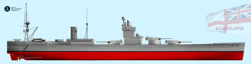
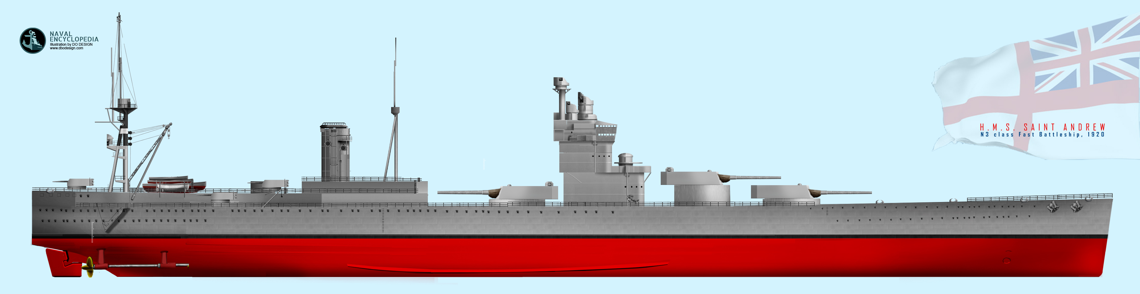
Eventually, although they had been approved, the N3 class battleships (prospective name generally admitted, St. Andrews class, in fact the four patron saints of the United Kingdom, with HMS St. George, HMS St. Patrick and HMS St. David). They would have been logically completed in 1922-23, and probably modernized, at least partially as were some QE and Revenge class; Even the Nelson class (which would have never been born) were modernized in the late 1930s.
With such main guns guns though, if the Washington treaty was never signed, the Royal Navy would have face even faster US and Japanese vessels, for the latter probably armed with the projected 51 cm guns for the precusrors of the Yamatos. The two Rodneys versus these four “saints” were just a budget, treaty-capped versions.

⚙ N3 class specifications |
|
| Dimensions | 249,9 x 32,3 x 10,1 m (820 x 106 x 33 ft) |
| Displacement | 48,500-49,300t normal – 55,000t est. FL |
| Crew | 1200 estimated |
| Propulsion | 2 shaft GS Turbines, 20 Yarrow boilers, 56.000 shp |
| Speed | 23 knots top speed |
| Range | Unknown |
| Armament | 3×3 18-in, 8×2 6-in, 6×1 4.7 in, 4×10 2Pdr Pompom AA |
| Armor (max) | Belt 15, Deck 8, Barbettes 15, Turret 18, CT 15, Bulkheads 14 in |
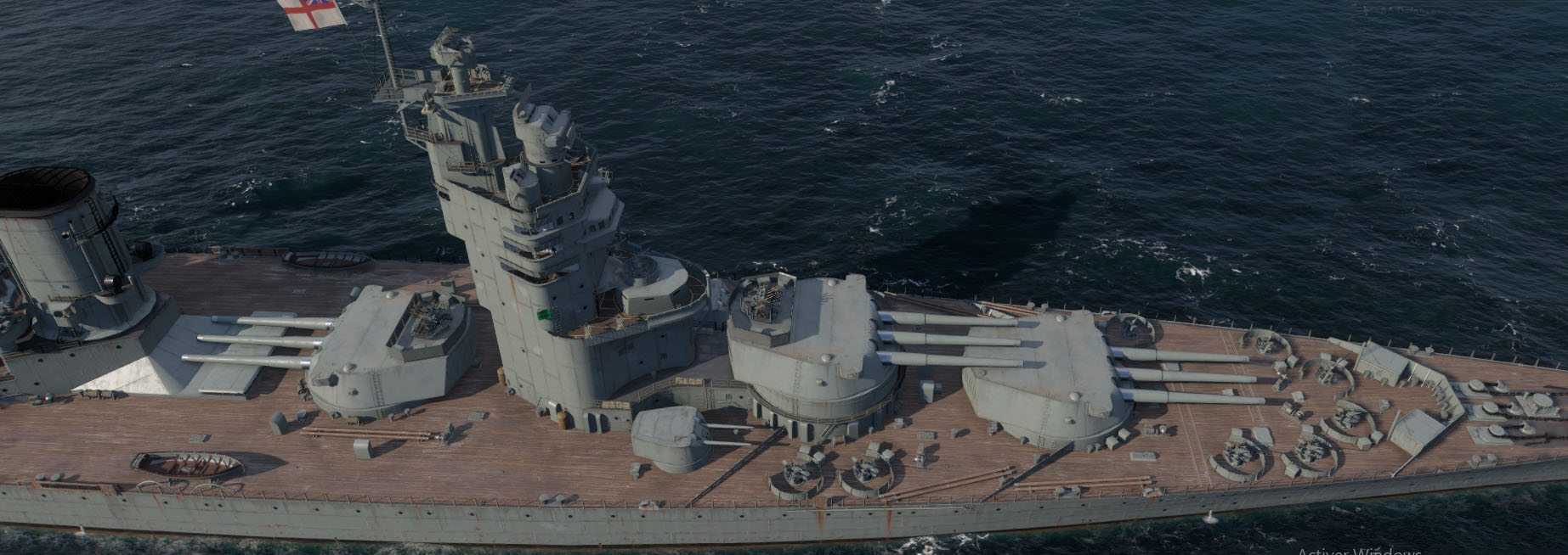
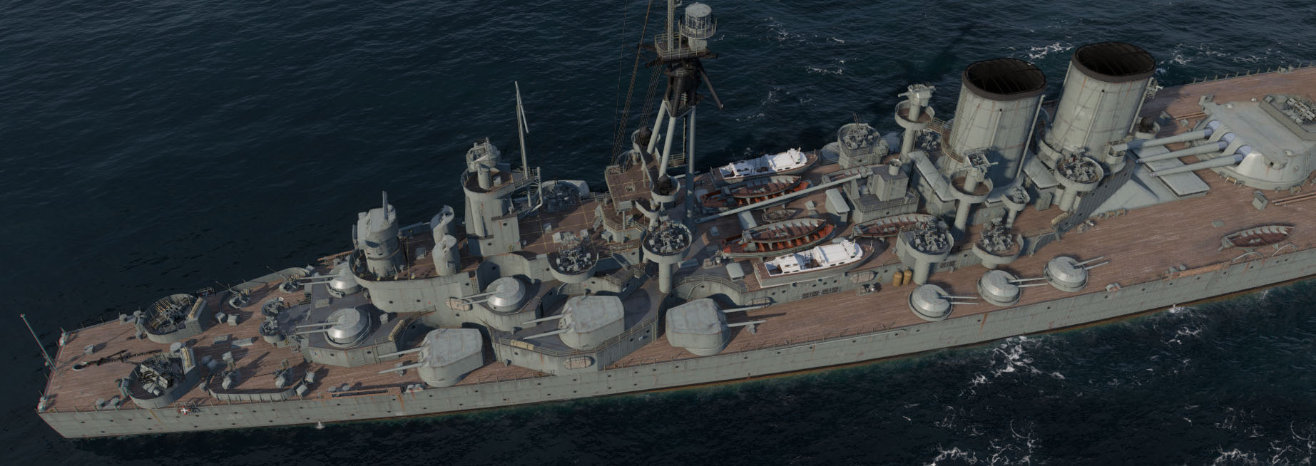
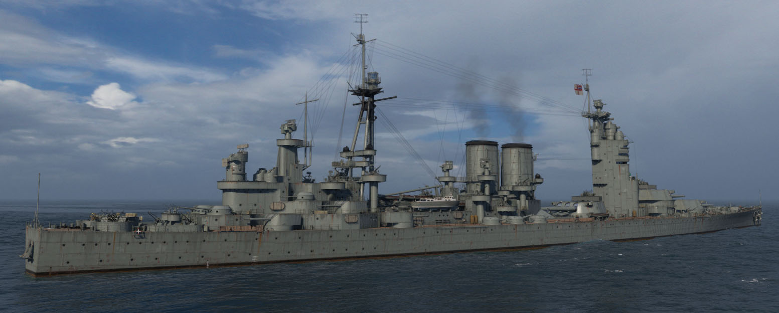
3D Impression
Note: This is a modification of the Nelson, not a proper rendition of the type.
Read More/Src
Navweaps pompom
Navweaps proposed 18 in guns
Navweaps 6″/50 (15.2 cm) BL Mark XXII
Navweaps 4.7″/40 (12 cm) QF Mark X
Navweaps 2-pdr [4 cm/39 (1.575″)] Mark VIII
Navweaps British Torps Interwar
Wiki
Video: N3 class Drachinfels
Gardiner, Robert. Conway’s All the World’s Fighting Ships 1906–1921
Brown, David K. (1999). The Grand Fleet: Warship Design and Development 1906–1922.
Campbell, N. J. M. (1977). “Washington’s Cherry Trees”. Warship. London: Conway Maritime Press.
Friedman, Norman (1985). U.S. Battleships: An Illustrated Design History.
Raven, Alan & Roberts, John (1976). British Battleships of World War Two from 1911 to 1946.
Model kits
On scalemates: 700-N3, HMS St. Andrew N3 1921 – Imperial Hobby Productions (IHP) 1:700
Gallery
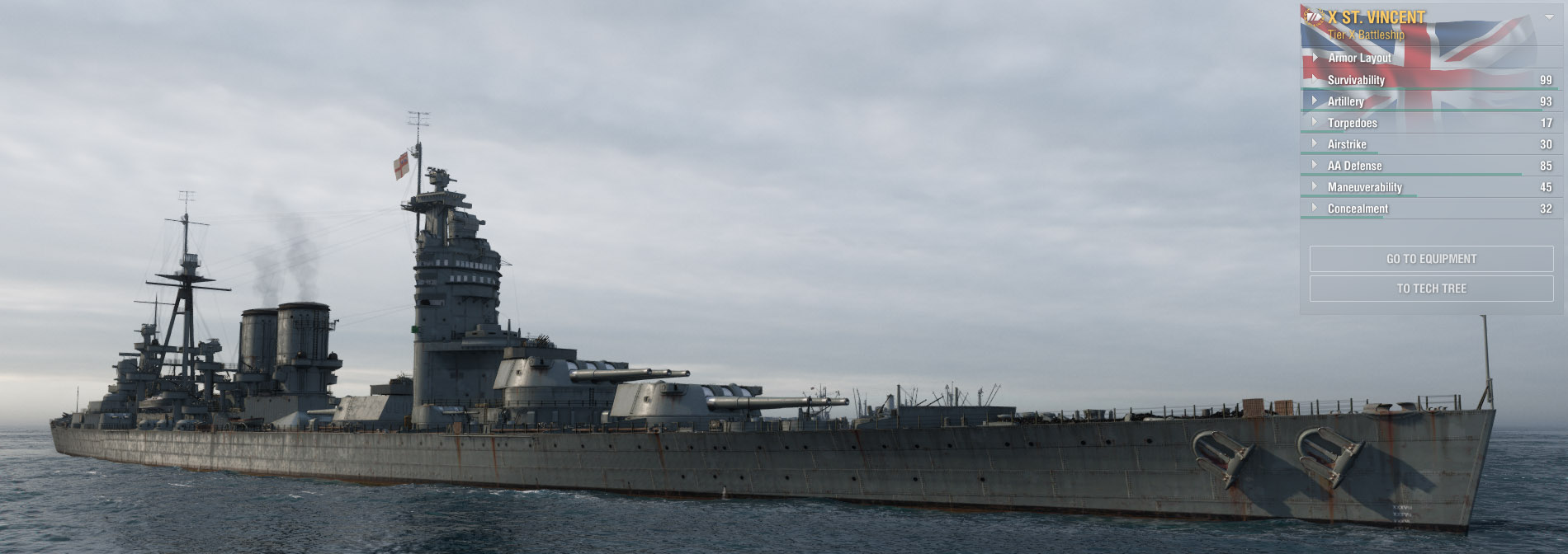
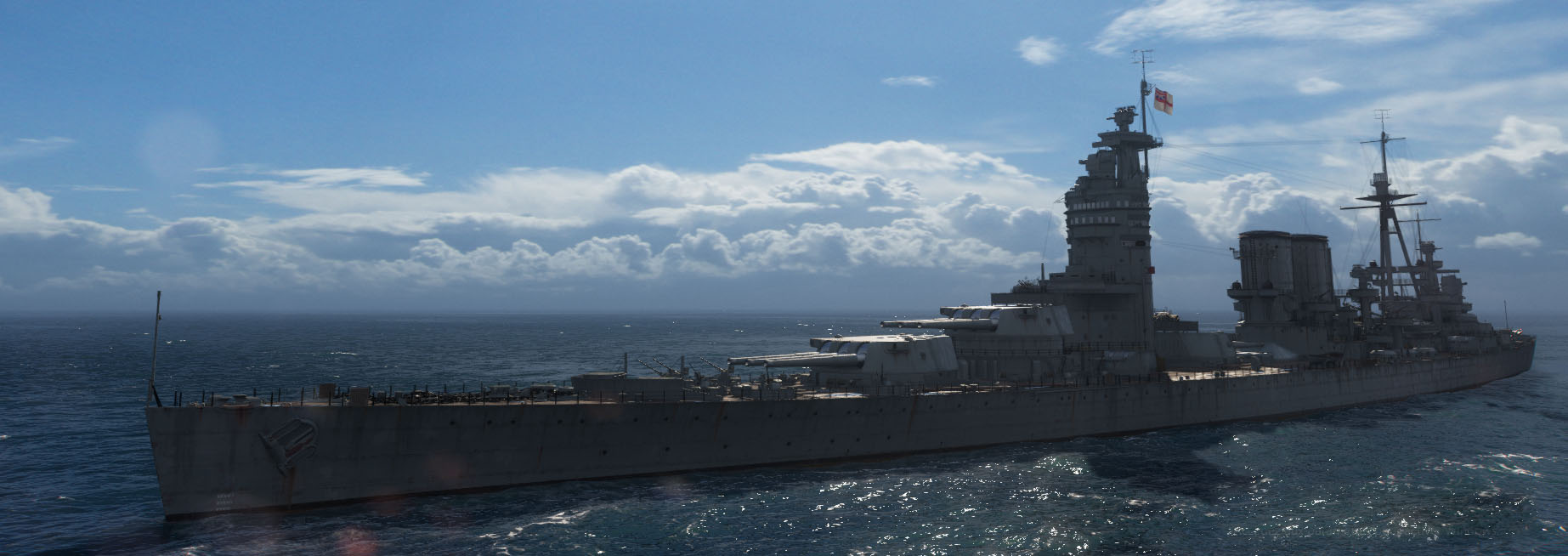
St Vincent renditions by World of Warships
 Latest Facebook Entry -
  X(Tweeter) Naval Encyclopedia's deck archive
 Instagram (@navalencyc)


 French Navy
 Royal Navy
 Russian Navy
 Armada Espanola
 Austrian Navy
 K.u.K. Kriegsmarine
 Dansk Marine
 Nautiko Hellenon
 Koninklije Marine 1870
 Marinha do Brasil
 Osmanlı Donanması
 Marina Do Peru
 Marinha do Portugal
 Regia Marina 1870
 Nihhon Kaigun 1870
 Preußische Marine 1870
 Russkiy Flot 1870
 Svenska marinen
 Søværnet
 Union Navy
 Confederate Navy
 Armada de Argentina
 Imperial Chinese Navy
 Marinha do Portugal
 Mexico
 Kaiserliche Marine
 1898 US Navy
 Sovietskiy Flot
 Royal Canadian Navy
 Royal Australian Navy
 RNZN Fleet
 Chinese Navy 1937
 Kriegsmarine
 Chilean Navy
 Danish Navy
 Finnish Navy
 Hellenic Navy
 Polish Navy
 Romanian Navy
 Turkish Navy
 Royal Yugoslav Navy
 Royal Thai Navy
 Minor Navies
 Albania
 Austria
 Belgium
 Columbia
 Costa Rica
 Cuba
Cuba Czechoslovakia
 Dominican Republic
 Haiti
Haiti Hungary
 Honduras
 Estonia
 Iceland
 Eire
Eire Equador
 Iran
Iran Iraq
Iraq Latvia
 Liberia
 Lithuania
 Mandchukuo
 Morocco
 Nicaragua
 Persia
 San Salvador
 Sarawak
 Uruguay
 Venezuela
 Zanzibar
 Warsaw Pact Navies
 Bulgaria
 Hungary

 Bundesmarine
 Dutch Navy
 Hellenic Navy
 Marina Militare
 Yugoslav Navy
 Chinese Navy
 Indian Navy
 Indonesian Navy
 JMSDF
JMSDF North Korean Navy
 Pakistani Navy
 Philippines Navy
 ROKN
ROKN Rep. of Singapore Navy
 Taiwanese Navy
 IDF Navy
 Saudi Navy
 Royal New Zealand Navy
 Egyptian Navy
 South African Navy


 Ukrainian Navy