
 IJN Heavy Cruiser 1942-45: Oyodo, Niyodo (cancelled), 11 more.
WW2 IJN Cruisers:
Furutaka class | Aoba class | Nachi class | Takao class | Mogami class | Tone classTenryu class | Kuma class | Nagara class | Sendai class | Katori class | Agano class | Oyodo
Tsushima | Asama | Tokiwa | Yakumo | Izumo | Kasuga | Hirado
The last IJN cruiser
She was the last cruiser class of the Imperial Japanese Empire (the fourth Agano class was really the last one), and by extension, the last Japanese cruiser since none was built since in the JMSDF. Initially designed she was designed as a hybrid scouting cruiser like the Tone class, but setup for wartime production. She was able to carry and operate six long-range seaplanes thanks to a 45-meter (147 feet) long aft catapult, screen forward of oceanic submarine fleets. However when completed in late 1943, the situation had changed completely and her 12 sister ships of the 1939 and 1942 naval plans were cancelled. Her military value was put into question as a “submarine leader”. She only performed a few missions but was stuck in Kure short of fuel when destroyed by USN aviation on July 28, 1945.
Development
A leader for IJN Submarine Sentai
The genesis of the Oyodo class cruisers was a prewar concept, which mirrorred the development of the Agano class. The latter were designed to lead destroyers and replace the old Kuma, Nagara and Sendai classes scheduled for replacement. This was an ambitious program with a dozen planned in the fourth Fleet Supplemental Budget. Similarly, Japanese strategists planned the use of their submarines in a way quite different than their axis partners, Germany. Instead of hunting down US commercial lines, which were mostly concentrated in the Atlantic, their goal was to hunt down the US fleet itself, preying on aircraft carriers, capital ships and cruisers, by using large and long range submersible types (see WW2 IJN submarines for more).

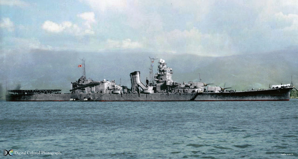
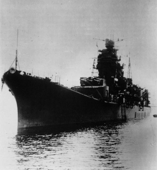
Oyodo colorized by Irootoko Jr. Few photos of this ship exists.
Previous experiences of submarine leaders
Back in WWI, the IJN trialled a first major Japanese submarine formation, the 4th destroyer squadron (sentai), formed on December 13, 1915, as part of the First Fleet. The name was counter-intuitive as it included two divisions of three submarines each and two mother ships called “Karasaki” and “Komahashi”. Submarine divisions were managed together with destroyer divisions in the fleet. On April 1, 1919, the 4th DesRon was reorganized into the 1st submarine squadron (sensuisentai). At first it consisted only of submarines attached to mother ships but as the models became larger and grew as their cruising range the admiralty felt it was time to replace the tender by a proper flagship. From December 1, 1921, Yahagi (Chikuma class) became such flagship, while Karasaki remained attached to the unit. A year later on December 1, 1922, the 2nd SubRon was formed, including a flagship, IJN Chikuma and a Tener (Mansyu).
The Japanese Naval General Staff faced a choice about blending the roles of flagship and tender or stick with by different ships, knowing the tender was more vulnerable and slower. Requirements for them were indeed too different. The flagship was required to have extensive communication facilities and accommodating headquarters, high cruising range and speed and powerful armament in order to oppose enemy scout ships. The tender however were expected to have much roomier accomodations to house all the submarine crews and very large replenishing stocks of torpedoes, shells, food, fresh water, and a complete workshiop to perform repairs at sea.
The Chikuma-class cruisers used for this could only perform as flagships after some modifications, but they were obviously ill-suited as tenders. Karasaki and Manshu were also unsuitable as flagships. however the situation was resolved by the lainching of a new generation of submarine tenders in 1923-24, IJN Jingei and Chogei: They combined a top speed of 18-knot speed, a powerful armament and extensive facilities to act as headquarters. Also in the early 1930s, speed and range of new Japanse cruiser submarines grew and the concept of submarine tender started to be obsolete, only kept as a pretext to be converted later as aicraft carriers, cheating treaties. The question return as how to lead these two formation with a more advanced flagship.
A new submersible flagship (1938)
On December 8, 1938, the minister approved a draft as part of the 4th fleet replenishment program calling for two 8,200 ton, 35 knot flagship for submarine squadrons. They were provisionally called cruisers “C” with numbers 136 and 137. On December 26, the program was presented at the 74th session of the Japanese Parliament. After discussion, it was adopted on March 6, 1939. According to this program the construction cost was estimated to 31.16 million yen (10,470,160 for the hull, 7,583,610 for the power plant, 12,609,871 for the equipment, 469,359 for the design and administrative expenses of the program).
The final requirements were approved in October 1938 and the fourth section of the Marine Technical Department was assigned the development of project “Cruiser C” under the leadership of Captain 3rd Rank Daisuke Ozono, supervised by the section’s chief, Rear Admiral Keiji Fukuda. C-42 project was completed by October 6, 1939 in parallel with C-41 (future Agano type) and so both shared a lot of elements. The project requirements drafted were as follows:
-Standard displacement of 9,800 tons;
-Main armament of two 155 mm triple turrets and four twin 100 mm DP turrets plus six twin 25 mm AA guns
-The number and location of torpedo tubes was not decided
-One dedicated 45m catapult (main feature here)
-Extensive facilities for six seaplanes (Model of 280 knots top speed, 2,000 nautical miles range at 200 knots)
-Four steam turbines rated for 110,000 sho working at 300 rpm and six boilers
-Top speed 35 knots
-Range 8,700 nautical miles at 18 knots
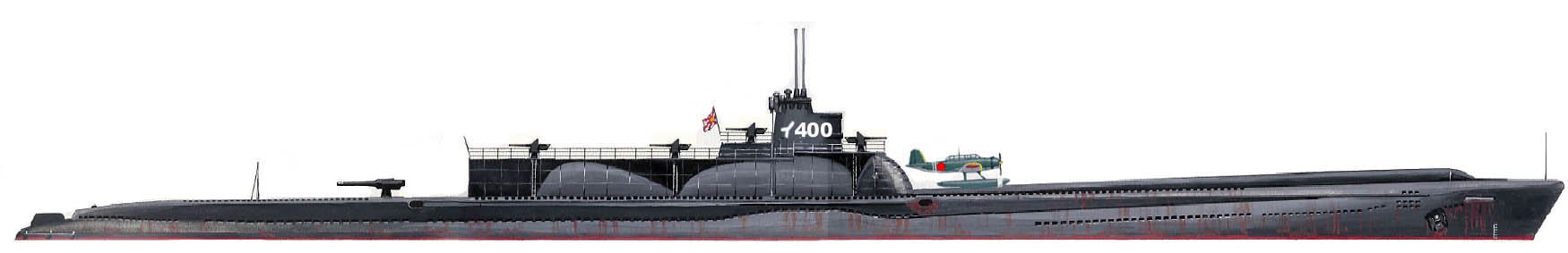
I-400, representative of these behemoth of cruiser submarines. Oyodo was to lead smaller wartime versions without a seaplane to spare space and complications.
The IJN’s submarine squadrons (sentai) were tailored to wage warfare at extended ranges, using onboard seaplanes themselves for some (this went up to one which carried three for an operation on the Panama Canal). These were to be coordinated by a cruiser acting as floating HQ and providing intel by screening for them, using an extra force of reconnaissance aircraft. At first it was believed the Agano-class cruisers could perform this role, but they proved too cramped for this. The hull could not accomodate more than two turrets forward making them too weak as flagships.
Construction
So in 1939, the Imperial Japanese Navy Staff discussed a new set of specifications tailored for seven hybrid cruisers, each leading a submarine squadron. Funding for the first two of this new class was approved as we saw as part of the 4th Replenishment Program. The lead ship was IJN Ōyodo, acted as a prototype.
Order for the lead ship, Cruiser C No.136, was issued to the Fleet Arsenal, Kure on December 6, 1939. It was planned to lay down her keel in June 1940 with a construction time estimated to 30 months. However, due to an extensive workload she had to wait to be laid down until February 14, 1941. On March 10, 1942, she was officially named “Oyodo” after a river in the prefectures of Kagoshima and Miyazaki. She was launched on April 4, 1942 and completed by January-February 1943 with a construction tim og 26 months, shorter that what was planned. The construciton of the latter was eventually cancelled.
Worst still, after completion, Oyodo was was now irrelevant as the initial concept she was tailored for has been terminated. There was no role for her.
Design
Hull construction & general characteristics
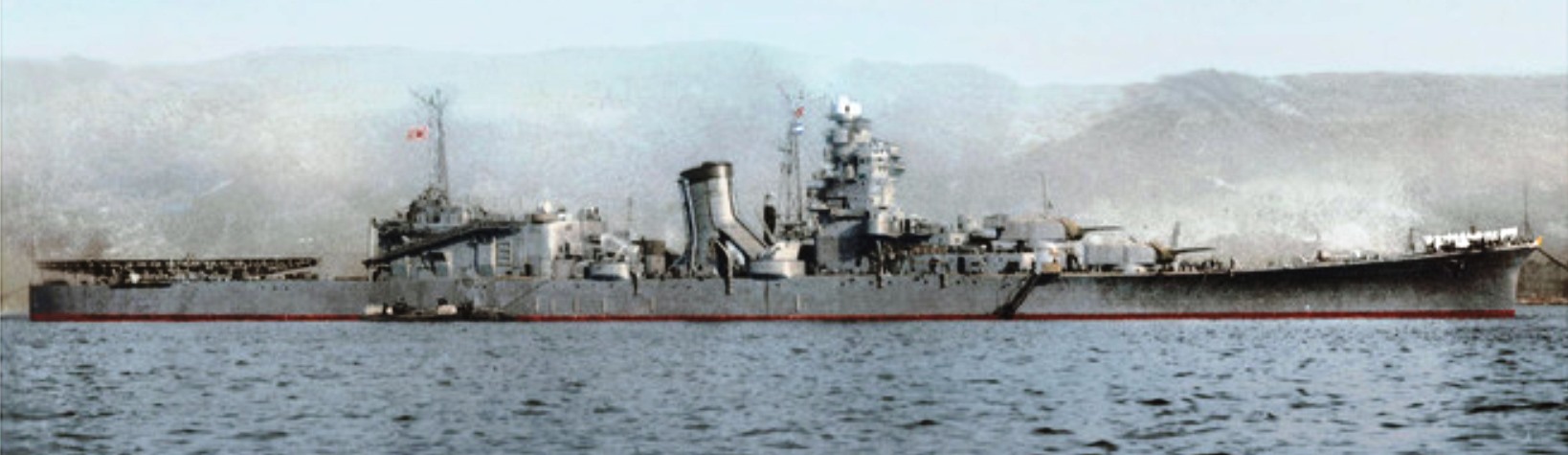
Nice HD view of the ship in 1943
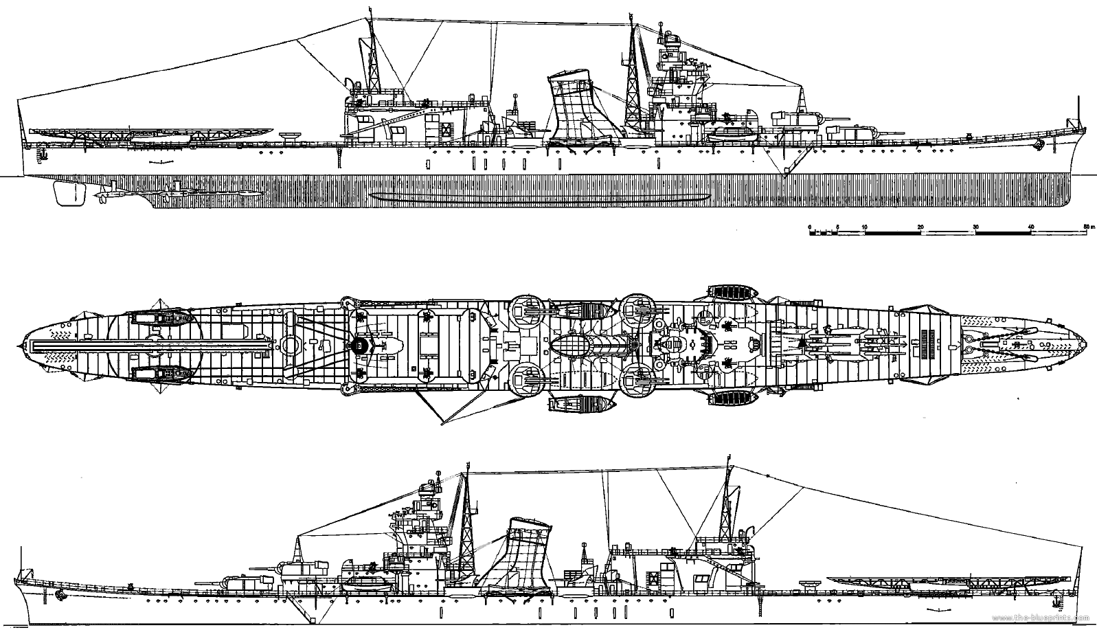
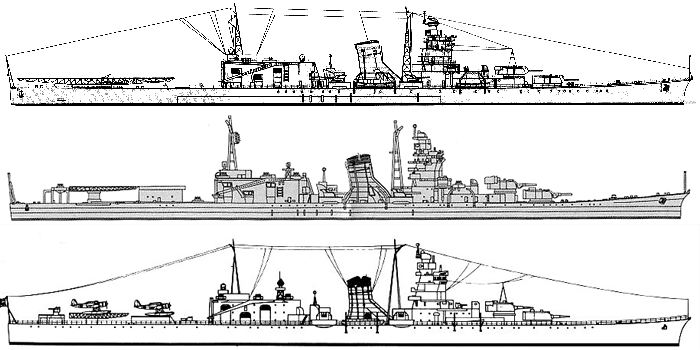
Instead of starting from a blank page, designers of the Ōyodo’ started from the well rounded Agano desig, modified and enlarged for her tasks. She retained the same general hull design, with a flush deck, bulbous bow, superstructure and armament improved. She was better suited to take a command role, and her armament was heavier, concentrated forward. Her final design showed a 189.73 meters (622 ft 6 in) long hull overall, 16.6 meters (54 ft 6 in) wide and with a 6.1 meters (20 ft 0 in) draft, a displacement 35% heavier, at 10,987 metric tons (10,813 long tons). She was given a metacentric height of 1.38 meters (4 ft 6 in) while deeply load.
Apart perhaps the prominent hangar aft and large catapult, the design of the Oyodo still kept with the same elegant silhouette as the Agano, with a flush deck hull and slightly raised prow, superfiring turrets, a tall bridge with a standard command deck and admiral bridge, extra facilities, but also a derrick foremast aft of it, which was new compared to the Agano’s tripod, and another derrick maintast on top of the hangar. The whole designed looked like a “stretched agano”, the larger deck surface alowed more AA to be added in the course of the war.
As completed she had a crew composed of 33 officers and 532 ratings.
About 32% of her normal displacement was allocated to the hull, 10% went to armor protection, 42% for the structure, 12% for the armament, 19% for the powerplant, wich gave her a power-to-weight ratio of 55.4 hp/ton. less than the Mogami, but more than ‘A’ cruisers (Agano). Normal displacement was initially 9,980 tons but after construction alterations it went to 10,330 tons and by February 1943 10,416.5 tons. Still engineers were satisfied this overload amounted to “only” 106.5 tons, a bit over 1%.
Flagship Facilities
Radio equipments according to the original project was quiote extensive for the time: It included nice transmitters and 21 receivers in order communicated with all the squadron submarines, as well as with the HQ for perfect coordination. Their actual composition differed during construction and in the end, there were 8 transmitters, including two LW bands (type 92 No.4 mod 2), and one LW-HF band (type 91 No. 4, mod 1), the five HF transmitter of the type 95 No.3 mode 1 and No.4, 5, thena Type 97 No. 6, and an experimental Type 97 No.2. This was completed by no less than 24 receivers: Three type 91, 18 DV-KV type 92, mod 4 and three kV type 97.
Receivers were located in two radio rooms, located on the roof of the seaplane hangar, and the other in the middle deck below the hangar, cabled being held by the mainmast aft on top of the hangar. Transmitters were in two separate rooms, one the front of the AA deck and the second on the hold deck, starboard side of the main battery. Six radio stations were equipped for radiotelephone communication initially, ten installed in the end: Fove transmitters (of 1.5-watt VHF type 90, 50-watt VHF type 93, and 30-watt MW No. 2) and then five receivers (VHF type 90, VHF type 93, SV-KV type 92) located at three radiotelephone posts in front of the AA deck, lower tier of the port superstructure and middle tier of the superstructure.
Propulsion
Kampon Turbines
The cruiser being larger than the Agano class (Type A), she had a more generous powerplant to compensate, helped by a larger hull. She was given a four-shaft steam turbine system like the Agano with a total output of 110,000 shp (80.905 MW). Initially, this powerplant was developed by the 4th section of the Naval Technical Department: Kansei Hombu, abbreviated as “Kampon”. These were to be same same as the Agano-class cruisers. But the output was 110,000 hp versus 100,000 due to a different layout of the engine and boiler rooms, 4 turbines, 6 boilers versus three turbines, five boilers, for a maximum design speed of 35 knots.
The four Kampon No.3-C model 1936 had a capacity of 27,500 hp each or 20.226 MW, at 340 rpm. They were located in four engine rooms separated by longitudinal and transverse bulkheads, over a total length of 32.2 m, 16 m for the front pair room, 16.2 m for the rear pair. Each unit included a combined high pressure (9250 hp at 3632 rpm) section, a medium pressure one (9150 hp at 3385 rpm) and a low pressure one (9100 hp at 2327 rpm) single-stream and double-stream. The gearbox had an helicoid gear with a single central gear and three drive gears from the turbines, having gear ratios of 10.68, 9.95, and 6.84. The front pair drive the outer shafts, the rear ones the inboard shafts. Total of the turbines was 162 tons, while the gearboxes totalled 112 tons.
Within the low-pressure turbines housing were located reverse turbines, with a total capacity of 27,500 liters, 6875 hp at 1471 rpm each, rotating the shafts in opposite direction to propellers rotation in forward speed. For cruising, two Kampon No. 3-A model 136 cruising turbines (6320 rpm) using a gear ratio of 4.03 were connected to the unit’s gearbox. Exhaust steam from the cruising turbine entered the other units and together produced 4250 hp (8500) at 150 rpm for a cruise speed of 18 knots. At full speed the cruise turbines were disconnected from the gearboxes, steam flowing directly to the first stage.
Other equipments
The exhaust steam went into four single-flow Uniflux condensers one for each turbine unit, which had a total cooled area of 3864.8 m². Each condenser was equipped with two steam jet pumps and steam jet coolers plus a feed water heater and one turbine-driven main circulation pump. There were two drain condensating coolers with pumps, and two desalination plants handling 96 tons of water per day each, also usable by the crew. They were installed in the forward engine rooms. Each of the engine rooms comprised also eight pressure, eight exhaust fans of 745 and 795 mm with a capacity of 9 and 11 m³/sec. respectively. They also had two fuel transfer pumps with a capacity of 30 m³ per hour, four fire and bilge pumps of 30 and 60 m³/h respectively, usable in different modes, as well as four oil coolers and eight oil pumps (forced lubrication system).
Steam Boilers
The turbo-geared units were fed with steam coming from six three-drum water-tube boilers. They were of the Campon Ro Go type. They comprised an oil heating system with superheaters and air preheating to accelerate their start. Operating pressure for the superheated steam was 30.0 kgf/cm², at 350 °C. Total area of the heating surface was 981 m² while the steam generating tubes represented 810 m² and the superheater 171 m². Total volume was 39.8 m³.
Each boiler was in its own boiler room, 9.8 m long. In turn these rooms were arranged in pairs. As fir the Agano class, steam was supplied in the same way although steam lines scheme diverged. The first Boilers rooms were arranged through their lines to feed the front pair of turbines, and the two others through lines closer to the keel fed the rear turbines.
Two vertical fans of 94 cm, with a capacity 22 m³/sec. completed the circulation of steam, and each boiler was assisted by main and auxiliary feed water pumps and water heater, fuel pump and fuel heater, oil pump and cooling water pump, and oil cooler and three fire and bilge pumps installed per boiler room. The latter were electric and one driven by the turbine and had a capacity of 30 to 60 m³ per hour. Combustion products exhausted through several exhaust lines converging into a single truncated funnel for all boilers, raked, and located behind the tower bridge.
Shafts and Propellers
Oyodo had four three-blade propellers. they had the same diameter of 3.6 m (), a pitch of 3.96 m (), and revolution speed of 340 rpm maximum. its full development area reached 7.56 m² and according to the original design, this was only 300 rpm, but with smaller (3.5 m) propellers initially. The shafts were lubricated constantly using a stock of fuel oil of 2,453 tons placed in 82 fuel tanks, representing a total volume of 2732.6 m³, located in the bow, stern, and sides, participating in the ASW protection.
Electrical Power
Electric power output usable when she had her engines cold and to run all vital system on board comprised three 400 kW turbogenerators and two 270 kW diesel generators (total 1740 kW combined). They produced direct current rated at 440 V same as for the Agano class. They were located in two compartments outside the engine rooms or the armored citadel, which made them vunlerable to flooding. The front group was located under the weather deck, in front of boiler rooms No. 1 and 2. The second was located in the lower deck, behind the engine rooms with a diesel generator (port) and two turbo generators (starboard).
Performances
Designed range was 8,700 nautical miles at 18-knot cruiser speed. But better results were obtained in the sea trials of January 1943: 10,315 miles at 18 knots in fact. Oyodo was still capable of running 7,714 miles at 21 knots and down to 3,861 miles at 28 knots, then 2,051 miles at full speed. These sea trials started on January 23, 1943 at Misaki Garden, Ise Bay. Oyodo managed to reach a top speed 35.199 knots based on 10,381 tons, her plant managing an output of 110,430 hp. at 340.3 rpm. The machinery was overheated and boosted later to 115,950 hp, 346.3 rpm, and she reached 35.31 knots which was her absolute limit. Handling tests were performed on February 18 which it was reported that at 34 knots, rudder hard over to port at 34.7°, her tactical diameter was 4.42 ship lengths along the waterline. On February 19, she managed a long run at 35.3 knots based on 10,467 tons and output of 111,220 hp, 339.4 rpm.
Armor Protection
The armor protection of Oyodo was based on the need to withstand direct hits from 6-in semi-armor-piercing (SAP) shells, and 250-kg bombs from 3,000 m. The Type of steel used ws composed of Chrome-nickel-copper containing 0.08-0.46% carbon, 2.5-3.0% nickel, 0.9-1.3% copper and 0.8-1.3% chromium. An analogue of NVNC chromium-nickel armor steel with the replacement of some of the scarce nickel with copper, has been produced since 1931 for plates up to 75 mm thick. High strength structural steel containing 0.25-0.30% carbon and 1.2-1.6% manganese. Developed by British David Colville & Sons (Ducol steel or “D”) in 1925 and stronger than HT, it was also used throughout the ship for structural armor.
Main Belt
The CNC steel main armor belt was 60 mm thick, and covered compartments over the machinery spaces, the rear electric generators and ammunition stores located between frames 92 and 155. It was 2.35 m wide above the waterline. The ship having a design draft of 5.95 m, it was supposed to rise by 1.56 m above the waterline.
An armored middle deck also made of CNC plates was 30 mm thick for the amidship section, 28 mm (1.1 in) on both edges, and 2 meters in width. Forward the armored deck started where the citadel ended, enclosed with a 35 mm transverse bulkhead connected from below to the lower deck. The aft 35 mm bulkhead (1.4 in) descended to the hold deck level. The 5-meter section between the lower and hold deck was given an increased thickness, up to 50 mm, as it was the aft wall next to the ammunition store.
Citadel
The citadel ran from frames 55 to 92, divided into two unequal parts. The forwards section was between frames 55 to 83 and covered the ammunition storage, so quite serious protection including an internal armor belt which was 2.6 m wide (10.2 feet), assembled from CNC wedge-shaped plates. It was 75 mm thick (3 inches) at the top, 40 mm (1.57 in) at the bottom. From above, it was combined with a 50 mm (2 in) armored lower deck also in CNC, connected from below and resting on the double hull bottom.
The aft citadel section, frames 83 to 92, protected the 6 in and secondary guns along with the second radio room. It was joint to a 28 mm (1.1 in) armored lower deck. The forward part of the citadel was also bonded to the main armored deck by a 60 mm, tapered down to 25 mm bulkhead, the forward and aft section separated by a 10 to 16 mm (0.6 in) bulkhead, made of ordinary D steel plating.
Turrets, Barbettes, Ammo wells
The 6-in turret barbettes had walls of CNC steel 20 mm thick (0.8 in), with 25 mm (1 in) support rings. Below the middle deck, the barbettes were downgraded to a 35 mm thick ring, which was conical with 120° angled plates. Beyond the armored lower deck thickness was reduced from to 25 mm, but continued by a tube with 25 mm walls, inclined to 60°. Outside the barbette, elevators for the 25 mm and 100 mm ammunition went in tubes respectively in front and behind the barbette of B turret. About one meter above the lower deck, they were covered by CNC plates 55 mm thick (2.16 in) 35 mm front and rear plates.
Tower bridge
The bridge was protected by 40mm CNC steel plates forward, 20mm D steel plates on its sides and rear. It was enclosed at the top by 20mm CNC plating. Between the bridge and control posts, under the armored deck they were communication tibes with 8 mm D steel plates.
Funnels, exhausts, ventilation
The funnel bases were protected by D type steel metal sheet, 10 mm thick (0.4 in) front and rear. The sides received 16 mm plating, but also 30 cm below (11 in) and 70 cm (27 in) above the middle deck. Ventilation ducts of the engine rooms had the same protection all along their truncation. The steering control room was protected on all sides by CNC plates 40 mm thick (1.57 in) down to 20 mm at the front and 25 mm at the rear.
Middle Deck
The middle deck above them used a sandwich protection, with two layers, one upper 20 mm CNC plate and a lower 16 mm D steel plate.
The shell elevator was protected up to the middle deck level with 35 mm CNC plating (1.37 in) on all sides. The communication shafts between the engine rooms and steering gear were covered by 10-16 mm D steel plating. The aviation fuel tanks had 16 mm D steel plating as well.
Underwater Protection
IJN oyodo’s underwater protection was poor however. First off due to the reduced beam of just 16.6 m, there was of course no armored anti-torpedo bulkheads. Designers instead relied on high subdivision of the hull into many watertight compartments, an old and proven solution, many of these side compartments filled with oil or seawater. The double hull bottom had 94 compartments and space between this double hull and main hold deck comprised 159 subdivisions, while the rest of the hull above the hold deck had 28 watertight compartments that could be filled artificially by automated valves, used for counter-flooding. A total of up to 613.3 tons of water was supported to correct a listing port or starboard.
The machinery compartments were separated by a longitudinal bulkhead making it possible to continually operate avec after a single torpedo hit. However, with her tight waist, IJN Oyodo had little margin for stability. Calculations showed it could withstand the flooding of only one engine room and one boiler, listing to 15°. This is what happened on July 28, 1945, but the crew at the time was unable to counterbalance the multiple torpedo hits in time by proper counter-flooding, so the cruiser capsized as a result.
Armament
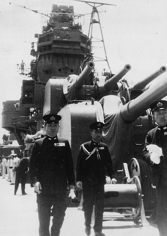
Oyodo’s armament comprised two triple 6-in guns (155 mm) at first, same as the Mogami-class, but as the war progressed, she obtained surplus twin 8-in turrets.
Main Battery
The main armament was composed on paper of the same six 155-mm type 3 guns as for the Agano class, but to free space aft, they were in two three-gun turrets. This ordnance was originally created under the guidance of engineer Chiyokiti Hata in 1930-32 for the Mogami-class cruisers, adopted on May 7, 1934. The gun was 60 calibers, enabling a muzzile velocity of 920 m/s for a maximum rate of fire of 7 rounds per minute. The barrel was of monoblock design and weighted 12.7 tons. The entire gun turrets with their turret mounts were those removed from the Mogami-class cruisers when they swapped to 8-in guns with the start of the war.
The rurrets were superfiring forward, “B” being on a barbette 15.8 m tall barbette, the other 13m (). They had a 300° traverse, the reliquate being blocked by a stopper to avoid hitting the bridge tower. This was quite generous arc of fire, the rest being brought by the ship’s orientation. Total weight of both turrets reached 360 tons. The turret mount was developed in 1932 with a ring diameter of 5.71 m. The barbette was protected by a circular armor in NVNC plates, 25 mm (1 inch) thick.
The fighting compartment housed the guns and carriages with hydraulic recoil cylinders and pneumatic knurlers. Distance between barrels was 1.55 m, too short for a side rloading apparatus so the bolt mechanism was rotated 45° to allow it. There were two hydraulic pumps working on mineral oil as a pressure of 70.0 kgf/cm² powered by two electric motors (100 hp each) to actuate hydraulic drives ans rotate the turret through a worm gear at 6° per second. It was also responsible of the elevation and depression through a vertical aiming mechanism with pneumatic drive at 10° per second. The same system powered the rammer, lifts and breech closure.
Ammunitions were 55.87-kg shells coming from racks below, fed to the reloading compartment using a roller conveyor, and pusher lifts rising in just 3 seconds, and so enabling a record 6 shells per minute. 19.5-kg charges were also delivered from a separate reloading compartment below, lifted by using bucket-type hoists and separated from the reloading compartment by double fireproof hatches. Thsy could be raised in 4 seconds (5 full charges delivered per minute). Each gun had its own pusher and bucket lift. Loading was performed at a fixed angle of 7°, mechanized, the bagged charges being loaded manually.
Four types shells types were used:
-Armor-piercing shell with ballistic cap type 91 (1.152 kg type 91 composition). It could penetrate a 100mm hardened plate from 15 km at 60°
-General purpose (HE) type 0, 6.8 kg trinitrophenol also usable against air targets on a 23 m () radius
-Illumination shell with parachute Type B
-Practice shell
The Oyodo carried 900 rounds, 150 per barrel, like on Mogami prewar. Maximum elevation was 55° and at 45 ° range was 27.4 km, shells climbing to 12 km. Each turret was operated by 24 men, plus 7 in the reloading compartment below, 10 in the bagged charges compartment so 41 per turret, 82 for both.
Secondary Battery
The medium anti-aircraft/ anti-ship duel purpose artillery comprised eight 100-mm type 98 guns.
They were located in four twin mounts abaft the funnel. These guns were designed in 1938 under the direction of Chiyokiti Hata, same as for Agano, an destined to replace the slower 5-in DP in widespread use in the USN as well as being a new destroyer gun standard. The barrel length was 65 calibers for a 1,030 m/s velocity and maximum rate of fire of 15 rounds per minute.
Its range was 19.5 km against surface targets, 14.7 km in AA mode (ceiling), with the most effective, accurate range between 11 and 14 km. Theu used twin mounts type A, 1st mod weighting 20 tons and a ring diameter of 2.28 m.
This was a semi-open mount, with 3 mm steel shielding designed against water spray but not shrapnel. The turret mount was hydraulically powered via an electric motor of 15hp with a 11.4°/s rate revolition and 16°/s elevation. IJN Taiho had similar guns, as well as Akizuki class destroyers, but with fully enclosed dome-shaped turrets. Regular ammunition load was 1600 shells of a single HE type, or 200 per barrel.
These 27.15 kg shells with 13 kg tip HE could be exhanged for a practice dud head. They came for ammunition rooms located under the armored lower deck, behind “B” turret barbette, to the upper deck via four bucket elevators, one for each. They were manually transported below and stored in fenders. Loading used semi-automatic rammers at all elevation angles. They also used fuse settings, separated.
AA Battery
The AA artillery in the original project comprised only six twin 25-mm type 96. Two were located in front of the bridge, four on the roof of the seaplane hangar.
But as construction (and the war) progressed, the need of a beefier AA was soon given priority and more AA guns were installed, starting by installing two more mounts on the hangar roof, when completed. Ammunition was stored in a room located between the barbettes of main guns, with 2000 shells per barrel, 24,000 then 36,000 total when completed. From there, the rounds travelled through a large bucket elevator to the middle deck and transferred via three smaller elevators then dispatched into the three main storage areas.
Fire Direction control
The ship was equipped with a main fire control director on top of the bridge. It comprised a Type 94 gunnery director for the main armament. The director housed a 6m (19 ft 8 in) span rangefinder but as a backup, the superfiring “B” turret was equipped with a 8-meter (26 ft 3 in) rangefinder.
The Type 98 secondary guns were assisted by two Type 94 directors, located at the base of the bridge. These included 4.5-meter span rangefinders, completed by an anti-aircraft fire control post with a ballistic analogic computer located under the lower deck.
The light anti-aicraft battery was assisted by three Type 95 directors installed on the forward bridge superstructure on various decks. Two direction finders type 93 No.1 were also installed at the rear of the compass bridge in separate rooms between the funnel and seaplane hangar. The three type 95 directors were located each next to their own AA group. They were relocated during completion to avoid fire damage. They all had type 97 stereoscopic rangefinders. The issues of the 25 mm AA guns, long derived from a 1914 Hotchkiss design, were known: Excessive vibrations, blinding illumination when firing, poor targeting optics and slow traverse/elevation. Fortunately the 100 mm were far more effective.
Until 1945, this was augmented: (to come)
Air group and Aircraft Facilities
Aichi E13A1 “Jake” of the Oyodo in 1944
IJN Oyodo was designed to carry six high-speed reconnaissance floatplanes, but the type was not disclosed. Four could be housed, with folded wings, in the massive aft hangar measuring 25.25 x 13.6 x 7.25m () and the remainder two on the rail system on deck. Handling seaplanes was done by using two 15.5-meter cargo booms, eaching with a lifting capacity of 6 tons. They were located aft of the hangar on pivot mounts, usable both to recover seaplanes and lift them to position on the catapult.
Aerial bombs which can be mounted on these seaplanes were stored in a room located inside the armored citadel, below the main deck and behind the engine rooms. Supply up to the upper deck used an armored elevator. Eighten 60-kg bombs No.6 were stored as well as two “special” 60 kg bombs and three 30 kg bombs No.3, plus 7.7 mm machine guns 57,600 rounds. Three gasoline fuel tanks were located aft, under the hold deck with a capacity of 98,780 liters (68.55 tons).
The main feature here was the special catapult type 2 No.1, model 10 installed at the stern designed in 1942. It was 44 m long for 65 tons making it the largest ever put on a IJN ship. It used compressed air to accelerate a 4.5-ton loded aircraft at 80 knots or 148 km/h or 5-ton at 70 knots/130 km/h (2.5 g acceleration). It was capable of rapid reload, for a launche every four minutes. Place in the axis it hade a 30° traverse port and the same starboard, 60° total, launching aft.
Oyodo’s planned air group
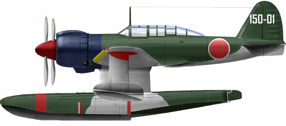
Author’s rendition of the planned Kawanishi E15K1 “Shiun”
For the mission at hand, the IJN drew specs for a high-speed seaplane (14-C) and proposed to the seaplane specialist Kawanishi right for the start, in July 1939. The company needed to provide twelve less spares to the No.136 and N°137 C-Class as well as four less spares for B cruisers No.132 to 135 (Agano class). As specified they needed a top speed of 518.5 kph (280 knots) and 3,700 km (2,000 nautical miles) range a 370 kph (200 knots).
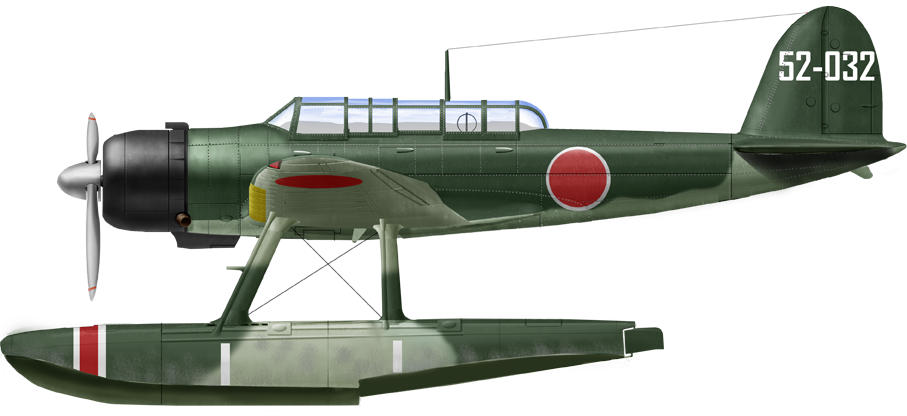
The first prototype called K-10 flew on December 5, 1941, using a single center float and underwing floats swiveling shut under the wings. This was supposed to lower the drag inflight, but was also the main source of issues with this model. On October 7, 1942 many modifications has been done and the first two prototypes were put into service as type 2 high-speed reconnaissance seaplane. When Oyodo entered service the first six pre-production were in service, and before they joined the cruiser, still being tested, two Aichi E13A1 “Jake” were assigned instead. By August 1943, the new model’s shortcomings and accidents being delaying production were officially introduced as the Kawanishi E15K1 “Siun” (model 11). But more problems reports had the production discontinued in February 1944 with only nine more delivered. It was lambasted for its low speed, excessive float drag, weak armament, and poor protection. Neither the Agano-class or Oyodo ever operated them, sticking to their “Jake” until 1945.
Author’s profile illustration Oyodo 1944
⚙ Oyodo specifications |
|
| Displacement | 8,164 t. standard -10 252 t. Full Load |
| Dimensions | 192.10 x16.60 x 5.9 m draft ( x x feets) |
| Propulsion | 4 shaft turbines, 6 boilers, 110,000 hp |
| Speed | 35 knots |
| Range | 10,600 nmi (19,600 km; 12,200 mi) at 18 knots (33 km/h; 21 mph) |
| Armament | 2×3 155mm, 4×2 100 mm DP, 12×25 mm AA, 2-4 floatplanes |
| Protection | 50 to 25 mm, see notes |
| Crew | 600-780 |
IJN Oyodo in combat
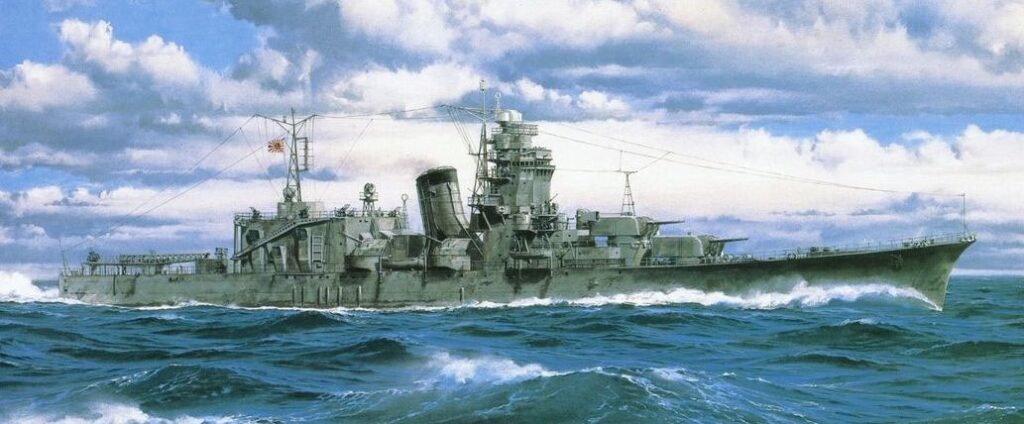
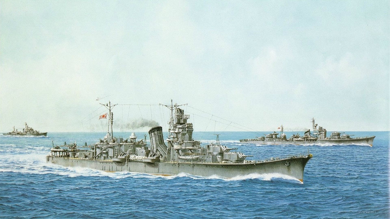
Artwork (boxart) showing Oyodo
After commission on February 28, 1943, she stayed in Yokosuka naval base for training under command of Captain Sadatoshi Tomioka (previously on IJN Aoba). On March 7, she moved to Tokuyama and arrived in Yokosuka training until April 15 in Tokyo Bay. She had been completed without any radar only receivd a Type 21 early-warning radar in April 1943 while still working up.
Since her designed role was no longer appropriate the Navy wanted to act as an ordinary light cruiser and transport. There were however some heated discussions, the some firmly insisting on her specific design as befitted a special task, notably as combined fleet flagship. But on April 1, it was decided to transfer her to the Third carrier mainly due to her range and good anti-aircraft defence. So she was assigned to the Third Fleet, joining the Mobile Force in May.
Her first planned operation was the invasion of Attu Island (11 May 1943) where she met a rapid reaction force of three battleships, two aircraft carriers and five heavy cruisers gathered in Tokyo Bay on 22 May. Attu however fell to US forces before even the force departed.
Oyodo would receive a short refit in Kure.
Then she was assigned a new mission of transport, loading troops and supplies on 9 July at Shinagawa and arrived at Truk in the Caroline Islands on 15 July. From there she sailed to Rabaul, arriving on the 21st and returning to Truk five days later, reassigned to the Third Fleet. On 29 August captain 1st rank (taisa) Sadatoshi Tomioka became her new CO. After the US carrier raid on Tarawa (18 September) she followed the fleet in response to Eniwetok looking for the US forces without success, and back to Truk on 23 September.

Oyodo in Yokosuka April 1944, colorized by Irootoko Jr.
Interception of American radio traffic suggested an attack on Wake Island so 17 October IJN Ōyodo departed with the fleet to Eniwetok, right planed for an interception, wihich never materialized. The fleet was back to Truk. Then, as her command facilities were at last recoignised, Vice Admiral Jisaburō Ozawa, Third Fleet commander, hoisted his flag aboard on 6 December. On 30 December, Ōyodo took part in a reinforcement of the garrisons at Rabaul and Kavieng, loading troops and supplies.
Back to Truk on 1 January 1944, Ōyodo was attacked and damaged by aicraft of Task Group 50.2. She had two crewmen killed, six wounded by strafing and near-misses. The 2 January saw her rescuing 71 survivors from Kiyosumi Maru torpedoed by an US submarine. She was back to Yokosuka on 16 February after the US invasion of Kwajalein. There, she loaded torpedoes and supplies for Saipan, and made a high speed run to deliver them on 22 February.
Conversion as command ship
Oyodo catapult modifications
She returned in Yokosuka for a full conversion as a command ship, which was completed by the start of 1944.
Additional weapons and equipment were installed: Her 45-meter catapult was removed and replaced by a conventional 25-meter Type 5 catapult. She received two Aichi E13A seaplanes and other deck modifications. The vacated hangar was completely refitted as headquarters with three storeys, tons of equipments for long range communications, map tables and housing for extra flagship personal. Two more tripe 25-mm anti-aircraft guns were installed at the stern and the same one deck, behind the hangar and on the bridge superstructure. All previously installed twin 25-mm machine guns were replaced new ones of a more moder, triple type. Also on deck, twelve additional single-barrel 25-mm were installed. Her mast was also fitted with a new Type 21 radar and Type 22 radars for fire control in the forward superstructure. A Type 13 aerial warning and surveillance radar was installed on the foremast as well.
Evolution of the design 1943-45
The Battle of Cape Engaño
The day after the refit was completed on 31 March 1944, Ōyodo became flagship of the entire Combined Fleet, but Kurita was replaced by Admiral Soemu Toyoda, which hoisted in turn his flag on 4 May. Ōyodo remained in Japanese waters until 11 October but on 29 September, Admiral Toyoda and his staff were transferred to new underground headquarters of the IJN in Yokohama as the aerial superiority of the USN as well as depredations of USN subs made fear that she could be sunk. By that time, she had received six additional Type 96 AA guns in single mounts by early October while her Type 22 radars were modified to be used for more accurate fire control.
IJN Ōyodo was back in the 1st Mobile Fleet (Jizaburo Ozawa) on 5 October. She departed Yokosuka on the 11th but was ambusged en route by USS Trepang. The latter fired six torpedoes but missed. She stopped an route to the resupply point of Yashima anchorage, on 20 October and headed for the Philippines to take part of Operation Sho-Ichi-Go. The goal was to defeat the American invasion using am ambitious and risky three-prone attack and a bait. This was a well-conceived plan that might have succeeded.
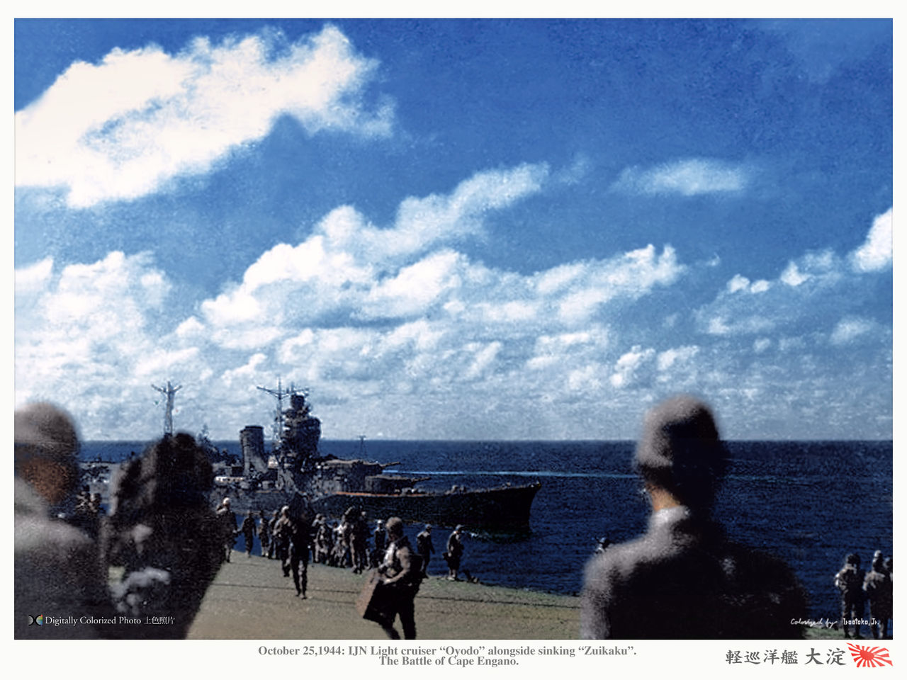
Oyodo seen from Zuikaku at the Battle of Cape Engano
Ōyodo was part of Ozawa’s Northern Mobile, precisely the “Decoy” Force, drawing north TF 58 away from the main strike. The bait force mostly comprised the remaining carriers, with a token air group, which were to be sacrificed in this mission. Ōyodo being the only one ship in Ozawa’s force with reconnaissance floatplanes, she launched both her E13A1’s in scouting and anti-submarine patrols.
On the morning of 24 October, the carriers launched all their forces to attack the US Task Force as distraction. They were all shoot down while inflicting no damage but succeeded on that Halsey’s Force departed to find them. US planes eventually catched and spotted Ozawa’s bait fleet at 16:40, 200 miles (320 km) east of Cape Engaño (northeastern tip of Luzon). Since it was too late to launch an air strike, Halsey took new positions to launch an airstrike on the morning. Ozawa reversed course during the night, assuming he would do exatcly that and started to head north drawing him out of the US landing area.
VADM Kisarazu on IJN Oyodo in 1944
On the morning around 07:35 contact was made again by US aviation of Ozawa’s force, and this allowed to redirect the airstrike (180 aircraft) already in flight 50 miles (80 km) ahead. In all, Halsey would lauch five airstrikes that day. The first strike saw IJN Ōyodo having two near-misses already. At 08:48 she received a bomb hit, badly damaging a boiler room. She still had the remainder ones and could follow the fleet and evade other attacks. Repairs were on the way.
At 10:54, Ozawa was forced to left the sinking IJN Zuikaku, his HQ, and naturally transferred his flag to Ōyodo which was wel fitted to the job and less conspicuous as target. However spared by the third attack, she was hit during the fourth, by two rockets from F6F Hellcat and shook by another near-miss. At 19:00 Ozawa learned about a vuagiard cruiser and destroyer US Force catching and destroying IJN Chiyoda, damaging and driving off Japanese destroyers rescuing survivors so Ozawa decided to turn back and engage them, sending the two Ise-class. He deployed his reconnaissance plans but was unable to find the US force and reversed course northwards again at 23:30, tryng to join Amami Ōshima, arriving on the 27th. Admiral Ozawa then transferred his flag to Hyūga while Ōyodo was sent in repairs.
Later Operations (1944-45)
On 29-31 October 1944 after some summary repairs, she was unassigned from CarDiv 4 group and detached, leaving Amami-Oshima for a transport run to Manila, arriving on 1st November 1944, and leaving three days later for Brunei Bay. On the 8th, after arriving she Joins IJN HARUNA, and the cruisers HAGURO and ASHIGARA ecorted by DesDiv 43’s (IJN KIRI and UME), departing Brunei on the 17th for the Spratly Islands.
CarDiv 4 (ISE and HYUGA), accompanied by the destroyer IJN SHIMOTSUKI were there, unloading troops and supplies after fleeing Manila due to US air attacks. 5th fleet’s Vice Admiral Shima Kiyohide also arrived from Manila on IJN HATSUSHIMO with ASASHIMO, KASUMI and USHIO from various divisions, transferring his flag to IJN ASHIGARA.
On 20 November, OYODO departed the Spratlys with the fleet for Lingga (22) and then departed with just the flagship Ashigara on 12 December for Cap St. Jacques, near Saigon. ASHIGARA went on to Camranh Bay but Aoyodo remained there. On the 24th, she left in turn for Camranh. At 09:00 she departed with ASHIGARA carrying RADM Kimura Masatomi and the destroyers KIYOSHIMO, KASUMI, ASASHIMO, SUGI, KASHI, KAYA for a raid on US American beachhead at San Jose, Mindoro in the Philippines.
The Raid on Mindoro
IJN Oyodo in the spring of 1944
On the 26 December durung their approach on Mindoro they are spotted and attacked by USN bombers. At 20:45, ASASHIMO had a near-miss, and at 2101, OYODO is bombed by B-24s at high altitude, but thanks to Norden sights, she is hit by two 500-lb bombs,one being dud, the otther not going through and only causing slight damage. At 21:15 KIYOSHIMO is sunk and at 21:24 ASHIGARA follows, badly damaged by a 500-lb bomb. At 21:30 KAYA is hit.
Air attacks stopped due to night conditions but alrady PT boats are on their way to intercept them. At 22:10, the KASUMI, ASHIGARA and OYODO spotted and fired at approaching PT-boats. One is hit, disabled, and the other fled. At 23:03, ASHIGARA and OYODO fires illuminating shells into Mangarin Bay and eventually sighted an American convoy. They closed in and 23:10, the destroyer IJN KASUMI fires four torpedoes at these troop transports but missed. At 23:15, IJN KIYOSHIMO is caught by USS PT-223 and sunk, one of the rare successes of the latter. She explodes and sinks, and by 23:26, KASHI and KAYA also fireed torpedoes claim sinking four transports (none reported sunk in reality). From 23:45 to 00:04, KASUMI, ASASHIMO, ASHIGARA and OYODO on the short sighted a supply dump on the mouht of Kasuang River and put it on fire. They also managed to damage the freighter JAMES H. BREASTED in Ilin Strait, still able to land its 600 Army troops. She would be bombed by possibly an US aicraft by error, havinf her cargo of gasoline on fire, and she would be later abandoned.
Operation “REI” in San Jose
The following 27 December, ASHIGARA and OYODO spotted and shelled USN ships identified as “gunboats”. At 03:45, ASASHIMO is attacked but undamaged and at 23:25 hit again. She was spotted by the submarine USS BAYA (SS-318, Cdr Arnold H. Holtz) and soon ASHIGARA and OYODO as well, as well as their escorting destroyers while returning to Camranh Bay. Holtz submerged to radar depth ahead of the approaching Japanese force and carried out his attack by sound, firing a full salvo of six at 22:07 from 3,200 yards, but missing the vanguard destroyer ASASHIMO.
At 1830 on the 28th, the fleet is back unharmed in Camranh Bay. The following day, Oyodo left via Cap St. Jacques to Singapore, reached on 1 January 1945. On the 8th her trip is revealed by codebreakers at the USN Melbourn Radio Unit which signalled OYODO, Ashigara and the 4th Carrier Division in Singapore. They next signalled a move to Camranh Bay to rendezvous with 43rd Destroyer Division but Oyodo remained between the 9 and 29 January in Singapore, repaired and refitted at the 101st Facility.
She departs for Lingga, staying until 6 February for the force to gather, and saild out with ISE, HYUGA, the destroyers KASUMI, ASASHIMO and HATSUSHIMO for Singapore.
Operation “KITA” (February 1945)
On 7-9 February 1945 Operation “KITA” is launched, basically a transport run for the Japanese industry. OYODO carried 300 tons of rubber, zinc, mercury and tin and 70 tons of aviation gasoline plus 159 oil field service personnel and other personal back to Japan.
On 10 February she is attached to CarDiv 4 and at night’s fall joins the “Completion Force” (Kan Butai) made of IJN ISE, HYUGA, OYODO, destroyers KASUMI, ASASHIMO and HATSUSHIMO back to Singapore.
On 11 February they are spotted by HMS TANTALUS which tried to attack but is bombed by the IJN air escort and flee. On the 13th in the South China Sea USS BERGALL (SS-320) spotted them through poor weather conditions off Hainan. He was forced to submerged and could not close beyond 4,800 yards, fires six torpedoes but miss. He is chased down by destroyers using their new larger depth-charges. Later that day they are also attacked by USS BLOWER (SS-325), firing five but missing again.
At 15:30 that day, while under a rainsquall OYODO launches a single floatplane which spots USS BASHAW (SS-241) on the surface, soon attacjed by HYUGA, having a 14-inch shell near-miss. On 15 February at 19:00, the Force arrived at Matsu Island Anchorage in Fukien Province (China) and the folling day, they depart via the Formosa Strait for Kure, close to Korean coast (which provides air protection), heading for Shimonoseki Strait. On their way they are met by USS RASHER (SS-269) alerted by “Ultra”. At 05:07 the latter spotted them by radar off Wenchow and surfaced in the driving rain, spotted one ship, firing six Mk.18 electric tprpedoes from 1,800 yards but misses as the Force changes course. The forces arrives at 21:06 at Chusan (Zhoushan) Island off Shanghai.
They depart against on the 18 to deop anchor at Shozen-To island in South Korea, departs the following day for Mutsure Jima and at last arrived at Kure on 20 February.
On the 25th Captain Matsuura Yoshi (on IJN IBUKI before)is the new captain of Oyodo.
Back in Japan (March-June 1945)
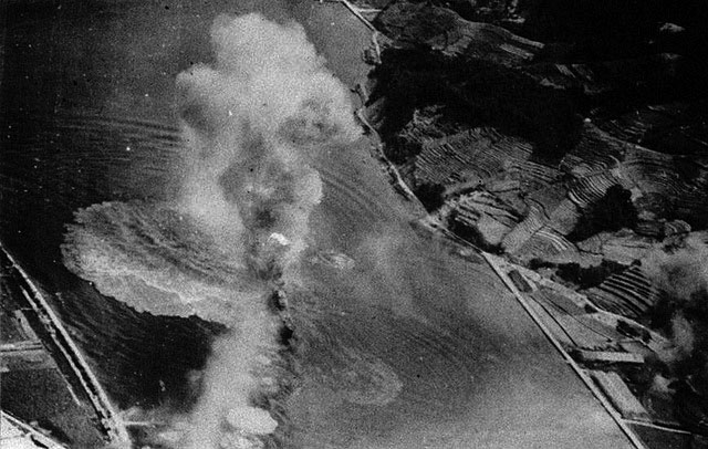
On 1 March 1945 Oyodo is assigned to Kure Training Force with her floatplane crew and service personnel transferred to IJN YAHAGI. On the 19th, TF 58 carriers USS ESSEX, INTREPID, HORNET, WASP, HANCOCK, BENNINGTON and BELLEAU WOOD made their first air attack one Kure Naval Arsenal with 240 aircraft between SB2C Helldivers, F4U Corsairs and F6F Hellcats armed with rockets and bombs rampaged the fleet at anchor. OYODO is hit three times with 500-lb bombs and perhaps ten near misses. One bomb weht through her port engine room (fire started) and damaged nearly all boilers. She had her starboard hull plating ruptured and start flooding, sinking by the bow with a 15° list. She is latter towed to Etajima, beached before any repairs could take plane. That day she fired her AA with little results and lost 52 sailors.
On 23 March she was drydocked, until 4 May. She then departs Kure for Etajima and the Inland Sea to be moored in Etauchi Bay, less exposed, off the western shore of Etajima. Fault of oil, she is stationed there as a floating battery and until mid-July partially camouflaged (unfortunately no record of this camouflage pattern exists), probably completed by netting. On 15 May Captain Taguchi Masaichi takes command, he would be the last.
The end
Under attack on 28 july
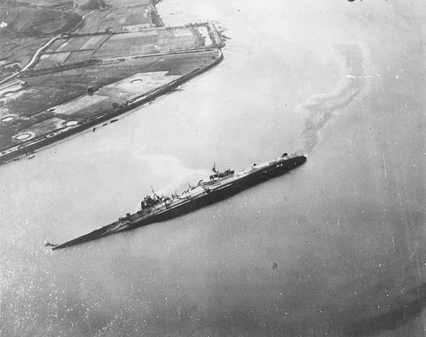
On July 24, 1945, a massive carrier-based air raid from the 38th operational formation (VADM McCain) hit targets of oppurtunities in the area. They soon spotted IJN Oyodo at 06:00. from there, and until 17:00 she is attacked by successive waves of about 50 Helldivers and Hellcats all armed with 500-1000 Ib HE bombs. Oyodo soon takes five direct hits of 500 Ibs bomns, two hitting the upper deck, close to the port side catapult, creating large entry holes, another two the central part, starboard, damaging the engine rooms and destroying a 100-mm mount. Another wen through the middle deck close to the forward superstructure, ravaing the encryption room and starting a firrce fire, ragung untik the 26th. She also had near-misses on her port side, holing her hull above the waterline. She was not flooded.
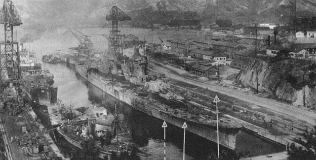
On the morning of July 28, she is attacked again by TF 38, this time, by 40 Helldivers from USS WASP and SHANGRI-LA. She taks several nar-misses on her starboard, close to the forward engine room and 5th boiler room, bursting the plating out and flooding. Counter-flooding had no effect so 25 minutes later by 12:00, she capsizes to starboard, listing at 80°. It was in shallow water so yhis left her port side over the water, by about 7.5 m. 300 drawn when she sank, the rest on orders of Commander Taguchi left her later in the afternoon. They had time to check for possible trapped survivors. Hellcats from USS MONTEREY came back layer and went to fire their rockets on the overturned cruiser. She is hit by two, creating holes and internal damage.
The end. Photo taken by a US plane in August 1945.
The war ended with Oyodo still in this position. On November 20 she at last is written off from the lists. She would stay her, a problem for merchant traffic, into 1946 and more of 1947. At last on September 20, 1947, she is reloated, towed to dry dock No. 4, Harima shipyard in Kure to be scrapped, from January 6 to August 1, 1948. As the the last survivors of the Imperial Navy’s cruiser, the modern JMSDF took inpiration of her design for large cold war ASW helicopter destroyers of the 1970-90s.
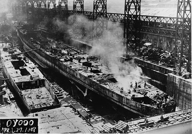
Oyodo’s scrapping in 1948
About the rest of the class
Cruiser C N°137
Cruiser C No. 137 was planned to be laid down at Kure in September 1941 and commissioned in March 1944. However, the keel laying was delayed until Cruisr No.136 (Oyodo) was out of the slipway. Moreover, after a meeting on November 6, 1941, due to incoming operation against Pearl Harbor, priority in shipbuilding changed. After Oyodo was launched on April 4, 1942, cruiser No.300 (the future Ibuki) was laid down in her place in the slipway on April, 24. Cruiser No.137 was suspended.
Cruiser C No. 137 was planned initially to be laid down at Kure in a separate slipway by September 1941 then operational by March 1944. However the yard objected to find a free slipway for her and so she had to be laid down in the same on dedicated to N°136. Both had their fate sealed when the first was delayed herself. As the launching of No. 136, was suspended after a meeting on November 6, 1941, pushed back to April 4, 1942, decision was made instead to prioritize cruiser No. 300 (IJN Ibuki), laid down on April 24. And so No.137 having little chances to be laid down before 1944, she was finally canceled.
Construction of Cruiser C N°137 (possibly named IJN “Niyodo”, the river in Kochi Prefecture) was indeed suspended on 6 November 1941, wating for her sister ship to clear the slipway. This played against her as the war changed drastically priorities and the prewar concept of Submarine Sentai soon proved irrelevant: IJN Niyodo was finally cancelled on 3 August 1942.
Thus cancellation came in accordance with an earlier proposal by the State School of Civil Engineering on June 30. She never got an official name.
It was not long before the remaining six of the 1939 plan were cancelled as the six of the 1942 plan.
Read More

Kawanishi “Shiun”, an interesting high speed two prop model that never was mass produced
Books
Bob Hackett, Sander Kingsepp. CombinedFleet.com IJNMS OYODO: Tabular Record of Movement.
Eric Lacroix, Linton Wells II. Japanese cruisers of the Pacific war. Annapolis NIP
Campbell, John (1985). Naval Weapons of World War II. Annapolis NIP
Jentschura, Hansgeorg; Jung, Dieter & Mickel, Peter (1977). Warships of the Imperial Japanese Navy, 1869–1945. NIP
Lengerer, Hans (2018). “The IJN Light Cruiser Oyodo”. In Jordan, John (ed.). Warship 2018. Osprey.
Polmar, Norman & Genda, Minoru (2006). Aircraft Carriers: A History of Carrier Aviation and Its Influence on World Events.
Stille, Mark (2012). Imperial Japanese Navy Light Cruisers 1941–45. Osprey.
Links
http://www.combinedfleet.com/oyodo_t.htm
https://ru.wikipedia.org/wiki/%D0%9E%D1%91%D0%B4%D0%BE_(%D0%BA%D1%80%D0%B5%D0%B9%D1%81%D0%B5%D1%80)
https://reviews.ipmsusa.org/review/japanese-light-cruiser-oyodo-super-drawings-3d
https://en.wikipedia.org/wiki/Japanese_cruiser_%C5%8Cyodo
Model Kits
You can trust Aoshima, Tamiya and Hasegawa to procure this segment in 1:700 and 1:350
First published on Jun 20, 2018.
 Latest Facebook Entry -
  X(Tweeter) Naval Encyclopedia's deck archive
 Instagram (@navalencyc)


 French Navy
 Royal Navy
 Russian Navy
 Armada Espanola
 Austrian Navy
 K.u.K. Kriegsmarine
 Dansk Marine
 Nautiko Hellenon
 Koninklije Marine 1870
 Marinha do Brasil
 Osmanlı Donanması
 Marina Do Peru
 Marinha do Portugal
 Regia Marina 1870
 Nihhon Kaigun 1870
 Preußische Marine 1870
 Russkiy Flot 1870
 Svenska marinen
 Søværnet
 Union Navy
 Confederate Navy
 Armada de Argentina
 Imperial Chinese Navy
 Marinha do Portugal
 Mexico
 Kaiserliche Marine
 1898 US Navy
 Sovietskiy Flot
 Royal Canadian Navy
 Royal Australian Navy
 RNZN Fleet
 Chinese Navy 1937
 Kriegsmarine
 Chilean Navy
 Danish Navy
 Finnish Navy
 Hellenic Navy
 Polish Navy
 Romanian Navy
 Turkish Navy
 Royal Yugoslav Navy
 Royal Thai Navy
 Minor Navies
 Albania
 Austria
 Belgium
 Columbia
 Costa Rica
 Cuba
Cuba Czechoslovakia
 Dominican Republic
 Haiti
Haiti Hungary
 Honduras
 Estonia
 Iceland
 Eire
Eire Equador
 Iran
Iran Iraq
Iraq Latvia
 Liberia
 Lithuania
 Mandchukuo
 Morocco
 Nicaragua
 Persia
 San Salvador
 Sarawak
 Uruguay
 Venezuela
 Zanzibar
 Warsaw Pact Navies
 Bulgaria
 Hungary

 Bundesmarine
 Dutch Navy
 Hellenic Navy
 Marina Militare
 Yugoslav Navy
 Chinese Navy
 Indian Navy
 Indonesian Navy
 JMSDF
JMSDF North Korean Navy
 Pakistani Navy
 Philippines Navy
 ROKN
ROKN Rep. of Singapore Navy
 Taiwanese Navy
 IDF Navy
 Saudi Navy
 Royal New Zealand Navy
 Egyptian Navy
 South African Navy


 Ukrainian Navy