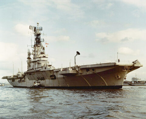
HNLMS Karel Doorman
Koninklijke Marine Aircraft Carrier 1948-1968 Dutch National Day ! HNLMS Karel Doorman (R81) was the only cold war Dutch aircraft…
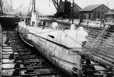
Barracuda class submarines (1925)
USN (1923-26)- USS Barracuda, Bass, Bonita (V-1, 2, 3, later SS-163-164-165) To start a new deep dive into US Navy…
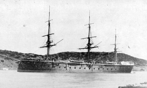
Vitoria (1865)
Spanish Broadside Ironclad (1864-1912) In its rapid expansion program, the Spanish Navy (Armada) chose to order it’s first ironclad in…
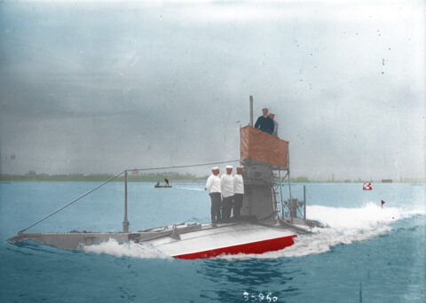
A class submarines (1902)
Patrol Submersibles 1904-1906, service until 1918. A-1 to A-13, 13 completed total The A class submersibles were directly derived from…
New Fleet ! – The Cuban Navy
The Cuban Navy already existed in some form as a regional Spanish fleet, certainly one of the strongest in the…
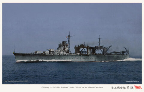
Mizuho class seaplane carriers (1938)
IJN – Mizuho, Nisshin 1938-43. The last IJN seaplane carriers IJN Mizuho and Nisshin were near sister ships and related…
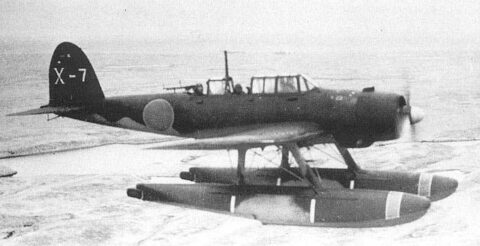
Aichi E13A Reisu “Jake”
Observation Floatplane (1941), 1,418 made 1940-1945 The Aichi E13A (“Jake” in allied nomenclature codes) was a long-range reconnaissance seaplane used…
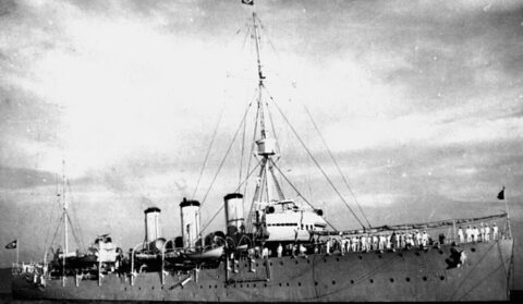
Bahia class cruisers (1909)
Bahia, Rio Grande do Sul (1911) service 1911-1945 The Bahia class were scout cruisers built for Brazil by British yard…

Kiev Class (1972-82)
Hybrid Cruiser Aircraft Carriers (1972-82) Project 1143 “Krechet” 1970-87: Kiev, Minsk Project 1143-3 Novorossiysk Project 1143-4 Admiral Gorschkov (Ex-Baku) The…
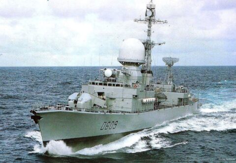
FS Aconit
ASW Frigate, F65 1973-1997 FS Aconit was a planned class of cheap but well armed, versatile Frigate, but ended as…
Naval Encyclopedia
Naval Encyclopedia provides a one-stop place for everything related to naval warfare through ships classes, going back to antiquity to the present day, with particular focus on WW1, WW2 and the cold war, with weekly articles and new fleets every month. This is a long endeavour, with future entries in opacity both in the top and side menus. Naval encyclopedia also goes through some civilian aspects (clippers, liners, oil platforms, naval tech in general) and battles/tactics as well.

 About Naval Encyclopedia
Naval Encyclopedia is the first online warship museum. She was laid down in St Nazaire Yard back in September 1995, launched in December 1996 and completed in March 1997, with 1000+ crew for now, and counting. Dedicated to the history of all ships of the industrial era and 20th century, so 1820 to 1990, but also earlier times. The main difference for this early period is to study ships types through some famous examples. After her last refit in 2023, the present ship has been repainted anew, modernized and made more appealing, ready for even more extensive service, hopefully staying in the current state for the next five years of service. Further improvements will be made if practicable. Numerous additions over the years also led to a complete machinery overhaul, new steam turbines and propellers.
Other ships from the same Yard