

Naval Technology – Every field.
⚙ From the origins to these days: Naval Technology
About a definition of naval technology
All good university-like expose starts with a definition: Naval Technology could be summarized as all ways devised to allow mankind seafaring. It’s quite ambitious in its scope and we can only guess the subject would fill such space that the present website, naval-encyclopedia, would be just a part of it. In fact we deal with naval tech in all these pages. There are a few posts specifics about construction or naval warfare innovations.
This section will focus on a particular aspect of naval tech, if related to naval warfare in general, sometimes veering on civilian aspects. Propulsion for example, belongs to both the civilian and military realms, as well as navigational devices, radars, sonars, and any other systems outside armament or protection, proper to military warships. So on the long run, we will see various subjects, posts treated in standalone (like naval artillery) or smaller subjects, like those displayed here, linked to a menu with anchors.
Articles
Naval Weaponry
- Ram
- Torpedoes
- Naval Mines
- Depth charges
- ASW rocket systems
- The sail: Types of rigging
- The sail: Teamwork & tricks
- Steam engines
- Naval Turbines
- Naval Boilers
- Order Telegraph (Chadburn)
- Armor
- Compartimentation
- Smoke
- Safety teams techniques
- Paravanes
- Chaff Launchers
- Electronic Warfare
- Hospital Ships
- Rescue Buoys
- Airborne rescue boats
- SAR tech (Search and Rescue)
- Long-views and Goggles
- Compass
- Maps and Charts
- Morse Projectors
- Wireless Telegraphy
- Radio
- Radars
- Sonars
- Ballistic computers
- Rangefinders
- Projectors
- Naval Drones
- Naval helicopters
- Latest entries
- WW2 American Naval Aviation
- WW2 British Naval Aviation
- WW2 French Naval Aviation
- WW2 German Naval Aviation
- WW2 Italian Naval Aviation
- WW2 Japanese Naval Aviation
- WW2 Soviet Naval Aviation
- Naval Aviation of the cold war
- Amphibians of WW1
- Amphibians of the interwar and WW2
- Amphibians of the cold war
- Hovercrafts
- Wing in ground vehicles
- Hydropters
Propulsion
Protection
Navigation, Communication, Detection and fire control
Naval-related Vehicles
- Naval aviation
- Naval Aviation of WW2
- Amphibious vehicles
(To come)
Veruschgleitsboote
Orlyonok
Also: Kaspian Monster, Lun.
(To come)
Naval Weaponry

Naval artillery
A whole separate dedicated page which contains:
- Antique weaponry
- Ancient Naval Cannons
- XVII-XVIIIth Cent. Naval Artillery
- XIXth Cent. Naval Artillery
- XXth Cent. Naval Artillery
- QF guns
- AA artillery
- Antimissile artillery
See also an article about the concept of “land battleship”. Another aspect of naval artillery is also coastal, hence a separated section of naval fortifications.
The ram
Treated here: The ram is an old idea that resurfaced in the XIXth century.
Ancient times:
Carthaginian ram of a ship sunk at the battle of Battle of the Aegates (First Punic War, 241 B.C.), discovered in 2010.
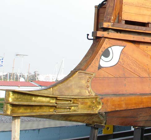
During the antique Mediterranean long naval supremacy contest, it was the spur ram, a separate piece generally in bronze, with various shaped that came to a tactical standard in around the time of Alexander the Great, and stayed that way until the time of the Augustean principate and Roman Empire. Its first use probably went back as far as the 8th Century BC and it was first recorded in use at the battle of Alalia in 535 BC.
It was fitted on all military galleys and used of course to “sink” enemy vessels, using ramming tactics helped by changing the rowing stance. In reality none really sank ever since they were all-wooden built and their floatibility coefficient was such at the worst case, they broke in two, or were just submerged. The idea was to eliminate them from the rest of the action, many were also later captured. The ram’s size was also a good way to calculate its carrier galley. The roster monument at Actium (Aktio in Greece) which saw the combined Antony-Cleopatra fleet defeated by Augustus (and Agrippa) aligned a dozen bronze rosters of which only the stone socket shape remained today. By calculating these, archeologists confirmed allegations of ancient writers about the composition of the fleet, notably very large galleys’s existence for a long time contested by many historians, such as the “20”.
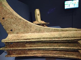
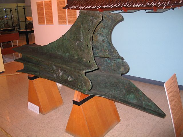
Roster of Alith, the world’s best preserved, rear view showing its socket shape, to be integrated into the prolongated spur where the keel and bow piece met.
The Roster of Alith (Israeli coast), a bronze ram buried into marine soil, is today the best preserved original bronze ram ever found. It probably belongs to an ancient Carthaginian “four”. The Roman fleet, a beginner in that field, war worried about its capabilities against the long and well trained Punic Navy which had quite a reputation at that time, being trained to battle for centuries against Greek fleets of the time and knew its trade full well. These vessels were fast and had excellent tactics. The pragmatic Romans recoignised this and started to place an armored belt along their trireme, quadrireme and quinqueremes, (as well as catapults and ballistae, and the corvus). They renounced speed and these fancy tactics so much so in imperial times, the ram practically disappeared and mostly became ornemental. But it stayed for centuries a symbol of naval power, as shown by the “roster plaza” close to the Forum where senators often spoke to the people and great decision were made public. Every marine building was also ornemented with rosters.
Survival until the enlightenment:
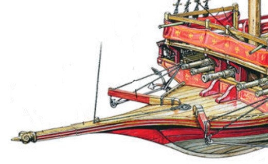
Ram tip and spur of a Holy League Spanish galley at Lepanto (1571) – Illustration by Tony Bryan, from Renaissance War Galley, 1470–1590, by Angus Konstam (Osprey Publishing, Bloomsbury Press Publishing)
The ram indeed was apparently still used by the Byzantines as shown is some galley depictions, but in some cases, it was no longer at the waterline level but sat well above, used mostly as a boarding passage for marine infantry. Classic medieval to renaissance galleys were always ended forward by a ram, but again, we have no clues of how it was used since artillery was often decisive, for example at Lepanto. In depictions, galleys faced each others, but they were found in melee combat and firepower eventually won the day. Outside of the Mediterranean, sail completely replaced rowing and the classic trade & war vessels such as the Cog, Carrack or Carvel had no ram. Galleons, a marriage of galley and carracks still had a reinterpretation of a basic galley hull but their “ram” mutated into a prolongated piece of the bow, carrying the foremast and symbolic figure, projecting in front of the forecastle. It was no longer offensive but still projected power, symbolic of the Prince’s might.
Renaissance in the industrial age:
The ram of HMS Polyphemus (1870)
Indeed, the rule of sails condemd the use of rowing and thus, of independent propulsion. It was now more difficult to “aim” a ship to another. In some rare cases ramming was used only if all conditions were assembled, and as a preamble of a boarding, but the schock was detrimental to both vessels and ofter bordered to desperation. The age of steam completely changed naval tactics. With this new source of power ships were autonomous again from the wind, despite a long transition (1850-1890) seeing sail and steam combined. In 1840, French admiral Nicolas Hippolyte Labrousse proposed building a ram steamship. In 1858, Dupuy de Lôme designed the ironclad “Gloire” with a ram and CSS Virginia’s ramming attack on USS Cumberland at the Battle of Hampton Roads in 1862 attracted much attention.
In 1860, the neoclassic style was very popular, and in its wake, the rediscovery of ancient naval warfare. An interest shown by the reconstitution by Napoleon III of a supposed trireme. But the appearance of the first ironclads in 1860 made ramming a potent tactic once again. Bows were reinforced and metallic rams attached to it in early generation ships, and afterwards built-in during construction on all. It was particularly clear at Lissa in 1864 when ramming was used wholesale in melee. It even became the definitive reference signal for all admiralties that the “ram was back”. It was from then a prominent feature on all cruisers, gunboats and capital ships, and stayed that way until 1914. In the 1870s it even trigerred a new wave of experiments such as the “torpedo ram”. The semi-submerged Polypheums was a good example of this.
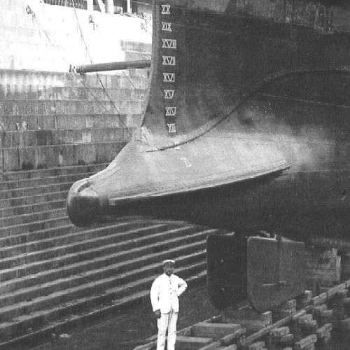
The ram in the 20th century:
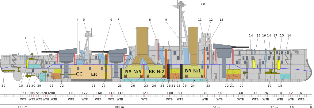
The reinforced ram of HMS Dreadnought is evident on this cutaway of HMS dreadnought in 1906
But at that time, apart HMS dreadnought ramming and sinking a surface u-boat almost by chance, the ram caused more sinkings by accidents (collisions) than combat. Like the protective nets at anchor, this idea soon diappeared. Tsushima already show QF gunnery and mines were more to fear, and Jutland showed long range naval gunnery ruled the day while both torpedoes and the ram in capital ships were innefficient. HMS Hood, laid down in 1919, had indeed no ram, as all the cruisers built as scouts in the 1910s. Ramming was still used at occasions during WW2, but again, against surfaced U-boats when the chance presented itself, and was often detrimental to the ship doing this manoeuver. Not all had reinforced bows. The small flower class corvettes, designed from northern atlantic whalers, had such ‘ice-breaking’ bows however. Nowadays, the “bow” is back, but only thanks to mathematics: The bulbous bow is an hydrodynamic feature recoignised for its ability to modify the water flow and increase the ship’s penetration, improving its general hydrodynamic qualities. It found its way in many warships as well for the same reasons. It’s a second return, but no longer as a weapon.
The bulbous bow of USS Lexington during her reconstruction in 1925, one of the first time that principle was applied.
Torpedoes
Naval Tech: Torpedoes
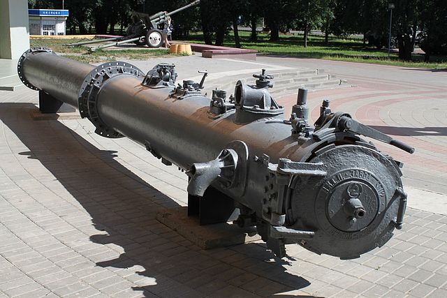
The origins: 1960s Luppis locomotive torpedo
Early Torpedoes: Whitehead 1880-90s
British Torpedoes
Austro-Hungarian Torpedoes
Italian Torpedoes
French Torpedoes
Italian WWI torpedoes
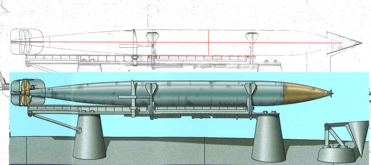
Comparison between the original drawing of the time (1895) and the dust jacket by V.M.Gay from the text of the Italian submarines and underwater assault vehicles by Turrini-Miozzi-Minuto – USMM 2010
Torpedo Models
There was a single manufacturer for Italian torpedoes at the origin, and until the great war broke out: Silurificio Whitehead of Fiume, the world’s oldest torpedo manufacturer, founded in 1860. It provided the standard types in use with Italian built and purchased German or British Thornycroft vessels:
-Spar Torpedo: According to Thornycroft designs, early 1877 proposals comprised a spar-torpedo vessel, however it seems regular torpedoes were favored early on.
-12 inches torpedo (305 mm) – Basically the Fiume Whitehead/Luppis model.
-14 inches torpedoes (356 mm) – Shared by all Italian TBs until 1910.
-17.7 inches torpedoes (450 mm) – All TBs from Schichau’s Sirio (1905). Strangely, Gabbiano (1907) went back to the 14-in caliber.
-21 inches torpedoes (533 mm) – None. They were introduced -(as for destroyers, even the 1923 Curtatone class still had 17.7 in types) in the mid-1920s and Sella class Destroyers (Even larger lead ships like the Poerio, Aquila, Mirabello, Leone, still had 45 cm tubes). The only exception was Cesare Rossarol, ex-B97 acquired in 1920, which had 500 mm tubes and German models.
-The Luppis torpedo (1875) was used in the Italian Navy as a single-propeller and compressed air (stroke 150 m), 27 kg. gun cotton warhead.
-The first modern mass-produced model was the siluranti A 34/356 W, built in Fiume by Whitehead in 1882. It was innovative by its use of two counter-rotating propellers, which stabilized it. This 356 mm (15 in) model had also a larger wahread of 34 kg. also gun cotton. Its air tank worked at 70 atmospheres, for a top speed of 22 knots over 400 m.
-The Siluranti B20 built in Berlin in 1884 by Schwarzkopff in bronze was also used by the Schichau models. Its tank worked at 90 atmospheres for 22 knots over 400 m and 20 kg warhead.
-The Siluranti B57 by Schwarzkopff and Rijeka (1888) had a tank at 90 atmospheres and 27 knots over 400 or 22 over 800 m and 57 kg. TNT wahread. It was the first with two settings.
-During WWI, a type A100/450 was recovered by the Austro-Hungarian Navy from the submersible Pullino grounded in July 1916. The Italians on their size recovered torpedoes carried by the Austro-Hungarian U12 that sank near Venice in 1915.
-The A140/450 resulting from it, built by Silurificio Italia after 1920: It was capable of 29-32 knots on the 6,000-4,000 m settings and had a 1140 Kgs TNT warhead of 140 kg of TNT, and air tank loaded to 170 atmospheres.
Prewar torpedo developments

Alongside the development or propeller, oxygen tank, warhead and body, progresses were made in locks, fuses, gyroscopes and when Italy entered the war more torpedo stocks were needed, not only the Silurificio Italiano was established in Baia, but a true R&D facility was created to try to improve speed, range, destructive capacity and accuracy. Tanks made in iron sheet were replaced by steel appeared and gun cotton by TNT in 1910 already. Its high stability and ease of processing were greatly appreciated.
In 1914 the Whitehead torpedo factory introduced an universal pendulum-type lock-device to determine the burst timing upon impact. It ensured operation at any angle of impact essentially. The 1877 Brotherood engine led way to the 1879 Brotherood-Whitehead using no longer a single central distribution valve but three cylindrical valves. In 1909, it’s speed, not warhread needs that led to a 533 mm (21-in) diameter, leading to the first two-cylinder sub-horizontal engine.
The adoption of swollen warheadswent back to 1896, preferred over refined ones thanks to higher speeds. The 1895 torpedo guide (by engineer Ludovico Obry) was purchased by Whitehead Silurificio in 1897, enabling automatic adjustment on italian torpedoes. This avoided lateral oscillations often causes of launch failure. Vertical fins were eliminated, notably as they increased friction in motion and if 1876 356 mm bodies prevailed, the need of a greater range and heavier payloads conducted Whitehead in 1889 to propose its 450 mm (17.7 in) and winning a competition in 1909 with a 533 mm.
WWI torpedo developments
At the beginning WWI, Silurificio di Fiume worked exclusively for the Central Empires, cuttinf its supplies to Italy as soon it declared war in May 1915. Following this, production in Fiume was transferred to St. Polten near Vienna, safe from Italian shellings. Only launching range remained in Fiume. These fears turned out to be well founded as on 2 August 1916 the whole area between Plase and Cantrida was shelled by the Regia Marina.
The factory produced some 1,780 450mm torpedoes, 64 torpedo launchers and 94 compressors at Rijeka shareholders approved bankruptcy of the company in 1918 and production as well as R&D was relaunched after Fiume went to Italy (Treaty of Rome, 27/1/1924) and Eng. Giuseppe Orlando became President. Inn 1928, it acquired full property as “Silurificio Whitehead di Fiume S. A.”.
The Rijeka factory was modernized in 1924, having 230 employees and producing 1,000 torpedoes in 1932. A launch & testing station was created in 1935, including to test airplane launches. But this is a story for the development of WW2 Italian Torpedo Boats.
Interwar and WW2
Apart early captured Schichau and Whitehead models and derived units, all were built by Silurificio Italiano S.rl.
-450 mm (17.7 in) modello torpedo for the Audace/Pilo, presumably same 17.7-in model as introduced on the 1905 Sirio class and shared by the PN class.
-Modello 140/450 for the Generali/Palestro/Curtatone classes: 29-32 knots on the 6,000-4,000 m settings and had a 1140 Kgs TNT warhead of 140 kg of TNT, and air tank loaded to 170 atmospheres.
-45 cm (17.7″) Si 200/450 x 5.36: Interwar Italian TBs.
-45 cm (17.7″) w 200/450 x 5.25: WW2 Italian TBs.
45 cm 200/450 Precise specs:
These were shared by torpedinieri and MAS boats 2,050 lbs. (930 kg), 17 ft. 7 in. (5.750 m) long, explosive Charge 441 lbs (200 kg), single setting 2,200 yards (2,000 m)/44 knots, powered by Wet-heater. The later W 200/450 x 5.25 was lighter at 1,896 lbs. (860 kg) and shorter 17 ft. 2.5 in. (5.250 m), same warhead by much greater range at 4,400 yards (4,000 m)/46 knots. Likely to be introduced on the Ciclone/Ariete classes during WW2.
German Torpedoes
WW2 German naval air torpedoes
The Kriegsmarine did not have an independent air arm and even the few floatplanes carried by cruisers and battleships, as the seaplanes patrolling the baltic and north sea were all under responsibility of the Luftwaffe. The employment of torpedoes launched from aircraft started unlike other nations, not in WWI, but in 1926, but development was in the hands of the Reichsmarine, and slow until the Luftwaffe gave it more attention.
The aerial torpedo LT I A1 F5b (Lufttorpedo LT I A1 F5b) emerged from these works, soon before the war. It was based on patents from Norway and Italy, was unreliable with a 50% failure rate. It had a significant dive after release and so was more useful in coastal waters.

The task of main antiship (torpedo) model was given to the excellent He 115
By February 1938, the navy bought a new and muxh improved Italian aerial torpedo and proceeded to replicate it knowing it would take until 1942 to produced about 100 torpedoes of this new type. Thus, in early 1939, production of the mediocre LT I A1 F5b proceeded anyway until there were 152 by June 1939 and 362 in the summer of 1940. The first Luftwaffe torpedo operation was led on 7 November 1939 in the north sea ordered by Naval Air Commander West, launching a “Kette” (3 a/c) in parallel formation prior to the attack for parallel tracks as a tactic to be sure of hitting something. It was unsuccessful, in part due to the primitive tools to determine the correct path of a fast moving target.
After the ice blocking seaplane harbors went off, the invasion of Norway proceeded and the delay left the command time to test a torpedo variant of the Heinkel 115 floatplane. Operations were carried out by “Ketten” or “Rotten” before dark, operating loaded with a torpedo each in an “armed reconnaissance”, basically “search and destroy” missions. Five flights were made this time more satisfactory overall.
The Luftwaffe however considered this a waste of time and preferred to use bombs, the traditional method. The Ju-87 Stuka in particular. Heinkel 59 and 115 were used for torpedoes, but had limited maneuverability to the drag caused by their floats, slowed down even more by the torpedoes, and thus making them slumbering on take off, with dangerous delivery tactics. They were just too slow to escape AA fire and took crippling losses. Conversion of pilots from the He 59 to He 115 for torpedo bomber units also changed the way the torpedo was to be used, creating significant problems until the design was changed and until fall 1941, results were meager.
The same year, interservice rivalry hampered development of a new torpedo or tactics, information being not carried well from the Kriegsmarine to Luftwaffe, both shoing little interest working together. The Luftwaffe in fact was fully reliant for antiship operations to dive bombing with stunning success in the Mediterranean in particular, which confirmed to Goering the inanity of using naval torpedoes.
Even the attack on Taranto changed little to these considerations, but Pearl Harbor was a wake up call, as well as the Swordfish attacks that crippled Bismarck in May.
It took until mid-1942 for a fully functioning torpedo to be adopted as the LT I A1 F5b was replaced with the better Italian F5w torpedo and from July 1942, only the indecisiveness of the Chief of staff General Hans Jeschonnek and same inter-service rivalry between delayed its use, at least until spring 1942.
Germany also asked Japan for several of their Type 91 aerial torpedoes and blueprints, carried by the submarine I-30 in Lorient by August 1942. The Japanese would deliver or failed to do so, Type 91 and 95 torpedoes and tubes, an automatic trim system, and even the complete Yokosuka E14Y. Still by the start of 1943, Luftwaffe’s torpedo bomber arm was just miniscule, with little to show for: Since 1939 not a single ship had been sunk solely by this method.
The F5w in Italian hands, notably carried by the trimoror SM.79 shown to be a formidable weapon used in large quantities and with some successes. Germans intensified torpedo bomber operations notably in the Mediterranean as the war started to go awry for them in this theater. Some units were based in Italy to shorten supply, but Italian Industry was unable to deliver the goods. The 450mm LT I A1 F5b meanshile was gradually improved until replaced by the LT II model in 1944.
In 1942, Hitler declare production of aerial torpedoes a matter of national importance at last, and work proceeded on the Japanese Type 91 mode, replicated between 1942 and 1944 as Luftorpedo LT 850, proving itself after Italy ceased deliveries of its Fiume model.
The L-40 aerial torpedo
Dr. Mario Zippermayr. sometimes “Zippermeyer” was born an Italian of Austrian parents and developed a great range of interests but its more remembered for his weapons research. He is remembered finding a solution to aerial torpedo usual issues. The standard German aerial torpedo was dropped from 50 meters (150 feet) in horizontal flight at about 300 km/h. (180 mph). Anything above or faster would have caused the impact damaging the torpedo’s steering mechanisms. Many misses were due in action to improper release in the heat if action, and sometimes improper tactics. Pilot hated low altitude and speed as this made them easy meat for AA. Researches went for a greater distance, higer altitude and mich greater speeds to improve survivability of the carrier. Final requirements called for a release at 1.5 kilometers from target, and at any height, angle or speeds up to 700 kph (435 mph), the max possible for a piston-driven aircraft at the time.
Dr. Zippermayr looked at the internal components completelky reworked them to absorb the punishment of these new delivery methods, and reworked the aerodynamics of the new torpedo as well. He created a new gliding surface balancing the torpedo in flight, a wing with pecial shape attached to the top edge of the torpedo, “V” as for a missile. Test showed the excellence of this design with a better center of gravity below its point of suspension, and the torpedo was shown to resist drops in excess of 720 kph from 1,000 meters. The Arado 234 in fact was modofied in January 1944 to carry these, but in April 1945 it was stopped. It is not known of archives survived enough to allow either the Soviets or US Intel to pass on these techniques to their own navies, but the development of antiship missiles in the early 1950s made these solutions obsolete anyway.
German Aerial Torpedo Data
the following aerial torpedo data is taken from Appendix 9 (p. 246) of Manfred Schiffner’s book “Torpedobewaffnung”:
German Torpedo LT1200: 5.57m x 533.4mm, 1,295 Kgs, Walter prop., Warhead 300 Kgs, settings 2500@46kts or 2100@50kts, drop speed 360, drop height 70m+/-30m
F5 5.16m x 450mm 750 Kgs. steam prop. 200 Kgs warhead, Settings 7500@22kts or 3500@33kts, drop speed 250 kph, height 40m+/-10m
F5b 5.16m x 450mm 750 Kgs. steam prop. 200 Kgs warhead, Settings 2500@36kts or 2000@40kts, drop speed 250 kph, height 40m+/-10m
src: https://www.battlefieldsww2.com/luftwaffe-torpedo-hexengrund.html
https://weaponsandwarfare.com/2020/04/25/germany-wwii-aerial-torpedoes/
US Torpedoes
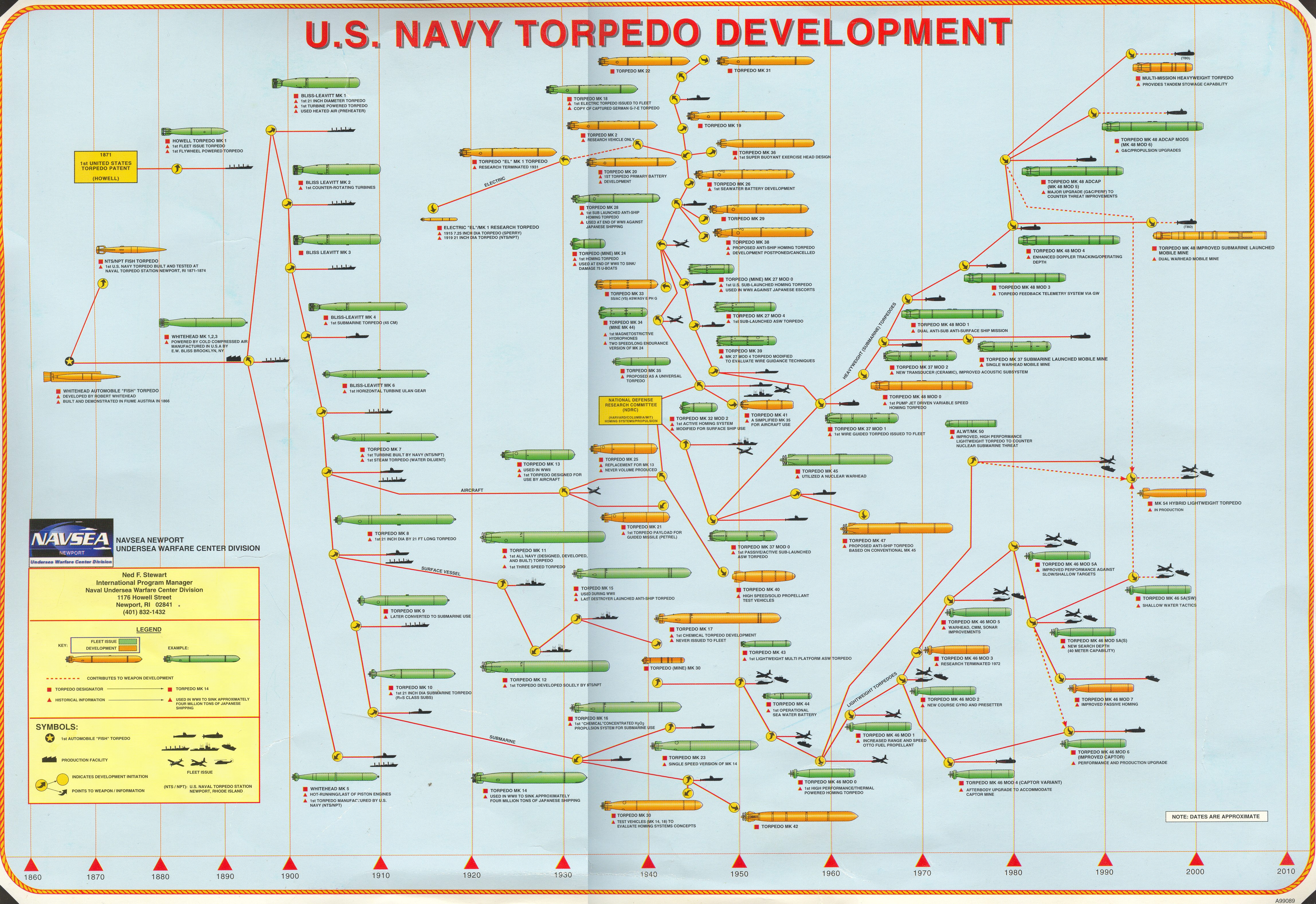
The full lineage of USN Torpedoes, including, ship/submarine/aircraft-borne. Scr Navsea, and kbismarck.com via navweaps
Japanese Torpedoes
18 in (457 mm) Torpedoes
The 457 mm types were used by WWI-era destroyers until the Mutsuki class. These were all of the Whiehead type, manufactured in Japan since the 1910 18″ (45 cm) Type 43. Likely those in use were the 18″ (45 cm) Type 44 No. 1 (1911) for the 8-8 program: Weight 1,585 lbs. (719 kg), 212 in (5.39 m) in lenght, 243 lbs. (110 kg) Picric Acid/Shimose warhead, Power/Range/Speed: 4,400 yards (4,000 m) at 36 knots, propelled by Kerosene-air fresh-wate.
21-in (533 m) Torpedoes

533 mm caliber, standard as in any navy introduced in 1918 for the IJN, ot 6th year Type torpedo found on the Momi, Minekaze, Kamikaze & Wakatake classes. In stock were 21″ (53.3 cm) Type 44 No. 1/2 (1911) but more likely these were 53.3 cm (21″) Type 6 (1917). The latter wighted 3,157 lbs. (1,432 kg) overall for 269 in (6.84 m) long, carrying a 448 lbs. (203 kg) Shimose warhead at 7,650 yards/35 knots or 10,900 yards/32 kts, 16,400 yards/26 kts. They were propelled by a Kerosene-air wet-heater unit. Kills were these were rare, as the destroyers of this generation saw often their TTs removed for additional AA and hostile encounters with other destroyers or cruisers were rare in their escort/patrol role.
24-in Type 93/95 Torpedoes

61 cm Type 93 torpedo found on the Mutsuki, Fubuki, Akatsuki classes, and all oxygen fuelled from the Hatsuhara and beyond. The Designer was Rear Admiral Kaneji Kishimoto, and Captain Toshihide Asakuma, and this started in 1928, then went on until 1932. The Type 93 became the nororious “secret weapon” unleashed by IJN destroyers and cruisers in WW2, which caused extebsive damage during the Solomons campaign expecially. The defective US Type 14 torpedo was in stark contrast with this. The Type 93 torpedo was dangerous to its user however but its effectiveness outweighed the risks anyway, claiming 23 Allied warships, 11 cruisers, 11 destroyers, and a fleet aircraft carrier and among these, 13 hits were fatal.
- Mass: 2.7 tonnes (6000 lb)
- Length: 9 metres (29 ft 6+5⁄16 in)
- Diameter: 610 mm (2 ft 1⁄64 in)
- Effective firing range: 22,000 m (24,000 yd) at 89–93 km/h (48–50 kn)
- Maximum firing range: 40,400 m (44,200 yd) at 63–67 km/h (34–36 kn)
- Warhead weight: 490 kg (1080 lb)
- Propellant: Oxygen-enriched air
- Maximum speed: 96 km/h (52 kn)
- Launch platform: Surface ships twin, triple, quadruple and quintuple bank.

-The Type 95 had a smaller (405 kg/893 lb) warhead (mod 2: 550 kg/1,210 lb) but was in essence a Japanese equvalent to the US Mark 16 hydrogen peroxide torpedo, shorter range but much faster. It could also be fired fro a standard 21 in submarine tube as well. Range was 9,000 m (9,800 yd) at 49–51 knots and 12,000 at 45–47 kn, thrice the Mark 14, at the same speed.
Russian/Soviet Torpedoes
M104 submarine torpedo tube.
-Standard 53-27 torpedoes (1927): Based on the earlier model 1912, 456 mm and the next 1917, 533 mm pattern. It was developed domestically in the so-called Ostekhbureau. The 1927 model had a 3,770 lbs. (1,710 kg) warhead, an overall Length of 22.97 feet (7.0 m), and explosive Charge of 584.2 lbs. (265 kg) and a Range of 3,700 m at a top speed of 45 knots. The power was provided by a Wet-heater. Production stopped in 1935. They were allso used by surface ships. When introduced they had a poor range and models from the Whitehead plant in Rijeka (53F) were judged better.
-Standard 53-36 torpedoes: Design started in 1932 to replace the 53-27. First introduced in 1936, basically a modified 53-27 torpedo, quite unsuccessful and production stopped in 1938, just 100 has been delivered.
-Standard 53-38 torpedoes: Design started in 1936 over the Italian 533 mm torpedo purchased from Fiume in 1932 and a copy of the 53F model. It became the standard Russian torpedo of World War II.
Powered by a wet-heater, it carried a warhead 661.4 lbs. (300 kg). The torpedo weighted 3,560.5 lbs. (1,615 kg), and had an overall Length of 23.62 feet (7.2 m). Range was 4,270 yards (4,000 m) and top speed 44.5 knots, less than the 1927 model. But it was much more reliable and went farther, with a larger explosive charge. The engine could be setup to two other ranges and speeds: 8,750 yards (8,000 m) at 34.5 knots and 10,940 yards (10,000 m) at 30.5 knots.
The 53 Family was fairly large and the model 38 alone was declined into several variants: 53-38/53-38U/53-59/53-56V and -56VA models.
-Standard 53-38U torpedoes: Modernized version with a larger warhead (400 kgs). Some had a magnetic fuze, installed from 1942.
-Standard 53-39 torpedoes: The fastest torpedoes in the world at 51 knots. Propelled by an improved wet heater system they sacrificed range for extra speed and were often carried in submarines alongside standard models. They weighted 3,924 lbs. (1,780 kg) for an overall Length of 24.61 feet (7.5 m), and carried a larger explosive charge of 698.9 lbs. (317 kg) of Trotyl (trinitrotoluene or TNT). Their settings were: -4,370 yards (4,000 m)/51.0 knots, 8,750 yards (8,000 m)/39.0 knots and 10,940 yards (10,000 m)/34.0 knots.
-Electric ET-80 torpedoes: The first electric torpedoes denominated 533 mm (21″) ET-80, designed in 1939 but introduced into service by 1942-43, exclusively for Russian submarines. They weighted more than conventional models due to batteries, at 3,968.3 lbs. (1,800 kg) for an verall Length of 24.61 feet (7.5 m) and carried a large 881.8 lbs. (400 kg) warhead up to 4,370 yards (4,000 m) at 29 knots but left no bubbles track, which compensated fo the lack of speed.
Russian naval aviation used the -450 mm TAV-15 (1932): An Aircraft torpedo based on the shortened Pattern 1910/15 torpedo, launched from 6,500-9,800 feet (2,000-3,000m), with 3 drogue parachutes and the TAN-12 (1932). In 1939 they were gradually replaced by the wartime 45-36AV-A model. There has been planes to carry planes on large cruiser submersibles in the Pacific, but they were never realized.
Naval-related Vehicles
Amphibious vehicles
(to come)
Hovercrafts
(to come)
Wing in ground vehicles
(to come)
Hydropters
(to come)
Construction
Modern wooden ships
Concrete ships
“Pikrete” ships
Propulsion
The sail: Types of rigging
(to come)
The sail: Teamwork & tricks
(to come)
Steam engines
(to come)
Naval Turbines
(to come)
Naval Boilers
(to come)
Protection
The paravanes
A familiar sight on 20th century warships, which appeared and disappeared relatively quickly, like protection nets against torpedo attacks between the 1880s and the 1920s. With their appearance of winged torpedoes, suspended on superstructures, they look odd and familiar at the same time, but their role is somewhat a mistery for many: Paravanes has been a fad in naval tech, dedicated to mine and ASW warfare.
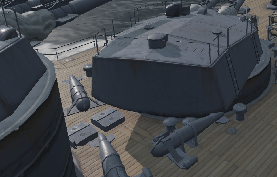
Paravanes on the deck of IJN Fuso (wow)
So basically, the Paravane is a towed underwater “glider”, a water kite. As a weapon, since it was given a warhead, the Paravane was used in anti-submarine warfare in general, and a British idea, developed from 1914–16 by Commander Usborne and Lieutenant C. Sir Dennistoun Burney. The project was funded by Sir George White, founder of the Bristol Aeroplane Company. It was initially thought of a way to destroy anchored mines, quite a deadly new weapon as shown by the Russo-Japanese war.
The principle was simple:
-The paravane was strung out and streamed alongside the towing ship, either from the bow or stern, but more likely the bow in order not to be perturbed by the propeller’s wake.
-The wings were designed to carry the Paravane away from the hull, creating a lateral tension on the towing wire.
-The idea was this cable could snag the cable anchoring a mine*, either severing it by sheer pressure or a cutter**.
-The mine was then bring to the surface where it could be fired upon and destroyed.
-If the mine cable could no be severed, the paravane would met the mine eventually at the end of the cable, detonating it*.
*A pull of about 7 cwt. the shears would cut a 1½ in. mooring-wire.
**The mine cable was guided into the jaws of shears or scissors made of special high-grade steel
**In that case, the Paravane did not need even to receive a warhead, hoping ot would hurt one of the sensitive Hertz horns.
In the 1920s the normal length of the towing lines was 56 yards and a ship carried several of these. Each one was a three three-strand steel rope made of 37 galvanized wires 0.049 in. in diameter. Their ultimate breaking strength ranged between 100 and 120 tons per sq. inch.
So in short, an anti-mine paravane was a towed underwater cable cutter. But the parralel one developed during WW1 was a proper weapon. There were basically three types of paravanes:
- The slow (16 knots), merchant-vessel type called “otters”
- The medium, heavy types used by capital ships
- The light type “fast” (26-30 kts) type used by cruisers and destroyers.
Destroyer paravanes, well used during both battles of the atlantic used a stern arrangement called a “depressor” to bring the virtual point of tow down to the required depth at the stern.
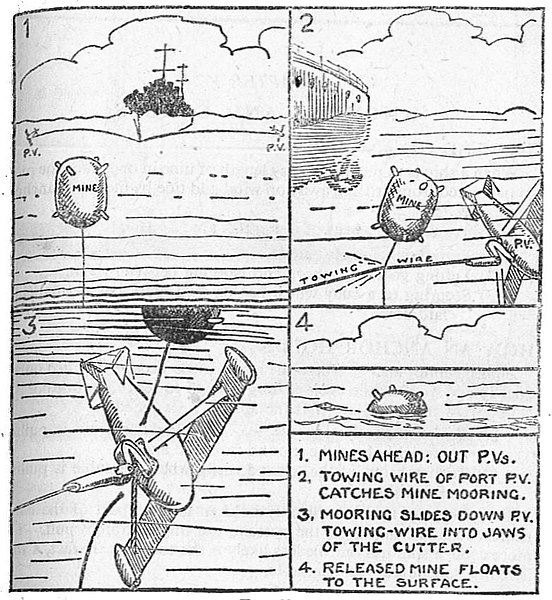
Paravane minesweeping principle – Seaman’s Pocket Book 1943
Anti-mine Paravanes were generally towed from the bow, using the “paravane chains” towed by the same capstans used for moorings cables. A ship towing two paravanes can ‘spread its wings’ of sweep over 200 feets. However for ASW paravanes, stern cables were used instead. They were maintained as low down as possible, with outboard ends kept about 100 ft away from the ship axis, creating a virtual swept a wedge-shaped track alongside the bow, at the level of the keel or below.
The first anti-submarine Paravane, called by Burney an “high speed sweep” was developed from 1915. Here are its characteristics:
-Horizontal and vertical tail fins to increase stability
-Depth-keeping mechanism in the tail (horizontal rudder actuated by a hydrostatic valve responding to difference in water-pressure)
-80 pounds (36 kg) TNT warhead
-Armoured electric towing cable.
The idea was that when meeting a submarine (creating tension on the cable), the paravane could be remotelly detonated alongside the hull, along three ways:
> By direct contact through a striking-gear on its nose
> When the load on the line exceeded a predetermined value (the circuit closed).
> By manual imput on the other side of the electric line via a hand-switch.
The Paravane was a relatively cheap and simple weapon (much simpler than a torpedo) and could be towed up to 25 knots (46 km/h). Its recovery was reasonably simple also. Paravanes were stored in many ships, mostly battleships and cruisers in both WW1 and WW2. However new ways of dealing with mines and radical improvements in ASW warfare made it obsolete during the cold war. There are indeed very few examples of submarine sunk by paravanes, if any. The Paravane was used for about 30 years and used by all major navies of the world, following the Royal Navy example.
It should be noted the idea resurfaced with the 1940 “Z battery“, this time to destroy planes, and using a rocket. It proved too a failure in operation. However it seems the US Department of Defense continues to have some interest in paravanes. The term is also used for fishing “gliders” today. Also the Paravane is distantly related to the Oropesa, a towed sonar fitted inside a submarine glider. The latter is used to vary the sonar’s position in depht and spread. The system appeared right at the end of WW2 and became widespread in the 1970s for minesweeping operations and ASW detection.
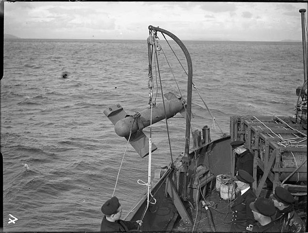 Paravane deployed by HMS Bentick off Greenock
Smoke screens in the Navy:
Although incendiary weapons were used at sea from the antiquity such as the Roman and Greek stinkpots and salpeter pots, and the early medieval Greek fire and its projector quite popular in the Byzantine Navy. This was times of relatively close warfare.
The earliest recorded use of smoke for the purpose of concealing a ship was the turtle ships in combat, with sailors burning materials creating a very thick smoke on the roof.
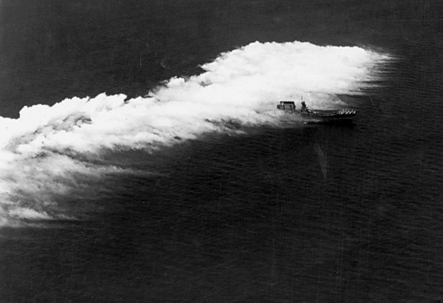
USS Lexington testing a smoke screen, 1930
However the use of naval smoke was proposed by Sir Thomas Cochrane in 1812, as much an asphyxiant. Later during the American civil war, R.E. Lee, which commanded a blockade created a thick smoke screen to escape USS Iroquois.
However it would would until the first years of the twentieth century for clear evidence of deliberate use of large scale naval smokescreens.
This became a tactic. As gunnery pushed the ship ten kilometres afar and more, one tactic was to conceal the silhouette to enemy spotters. Its use was regulated, learnt, and practices in exercises. It was already known and well used during World War I, and even more during World War II. Event the introduction of radar did not changed its purpose, at least until better technologies to precisely locate a ship were available.
Smoke screens were created by relatively lighter ships in order to conceal them or others under the same blanket. Cruisers and destroyers were prime candidates for this. They were fast and agile enough to spray their smoke on a large area.
Using smoke screens had one main use: Conceal one of several ships in difficulty, badly hit and escaping for example. This was used most of the time this way, sometimes with the effect of really saving a ship. That was the famous case of HMS Exeter, badly beaten by the Graf Spee and probably on the verge of total destruction when the two light cruisers present at the battle of Rio de la Plata concealed her retreat in a thick smoke. The Graf Spee was herself damaged and this was sufficient to break the chase.
The concealment indeed could hide destroyers, just waiting the best opportunity to launch a volley of torpedoes. Destroyers following in line could create a massive, high curtain of smoke capable of masking the real strength of a fleet, including the smoke plumes.
In was deployed when dealing with coastal fortifications also. Allowing to conceal the ship behind smoke to the coast spotting control, whereas planes, well above it, could provided fire corrections.
It was also (and still is) used to conceal an approaching amphibious fleet. Slow landing crafts were an easy target, therefore smoke could disturb the spotters enough to not be able to hit a single one before the landing was done.
Smoke screens were proficiently used in the Baltic for example, in all sorts of operations and by all participants. They were often laid by motor torpedo boats and patrol boats. The Soviet navy used smokescreens laid perpendicularly to the direction of the attack to cover their MTB approach, in a bent zig-zag. The tactic was to lay it close enough to the target for a massed torpedo attack, without exposing the approaching crafts.

HMS Gloworm against Hipper
Smoke screens were also used with great effects at the Battle of Samar. As Taffy 3 was attacked by the main Japanese fleet, sneaking in the Philippines (part of the battle of Leyte), destroyers not only put an heroic fight to keep the IJN ships at bay, but also generously blanketed the slow and vulnerable CVs, sparing them certain destruction.
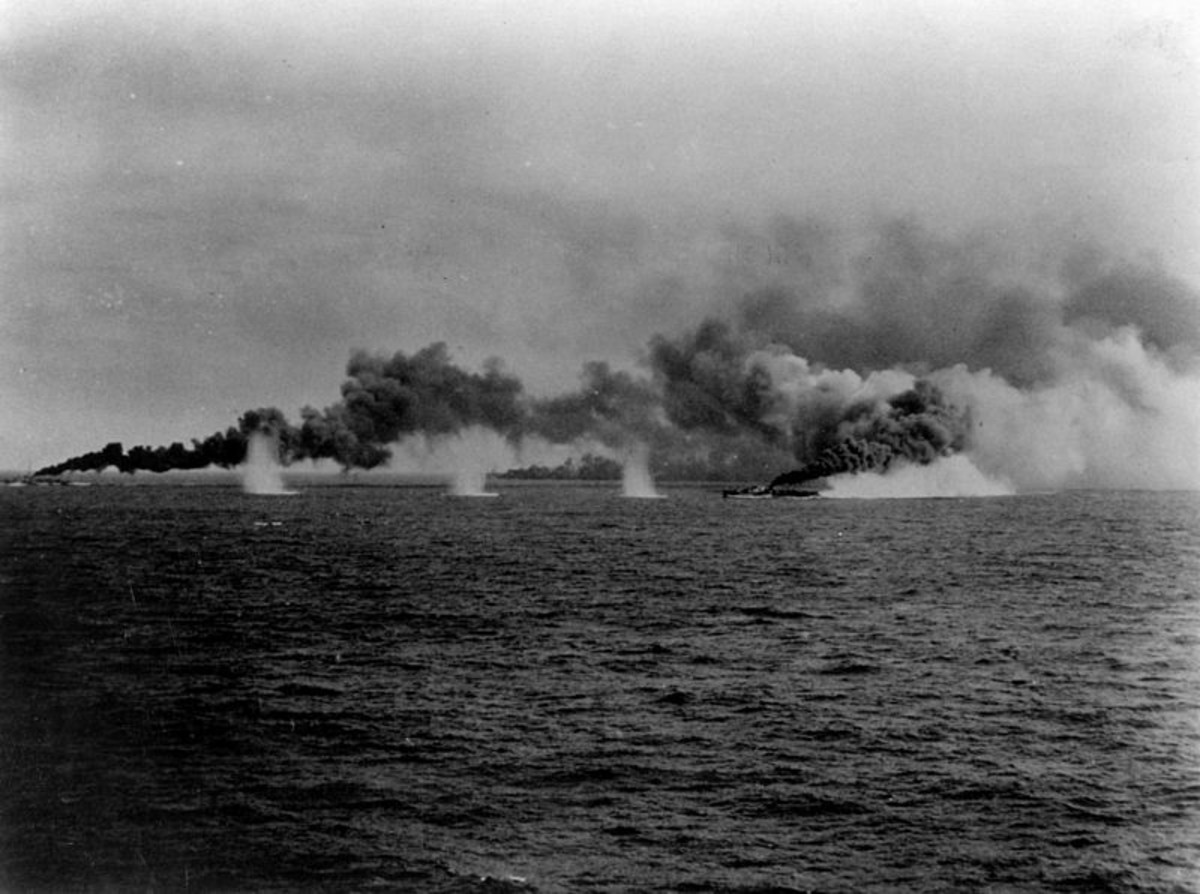
Battle of Samar
How it was done ?
In general, the most common way was the same tanks used in the cold war: Injecting injecting oil into the boilers to create black smoke, which exited from the funnel, or chemical canisters disposed at the stern (creating white smoke), which were mostly used by cruisers.
By using planes, and special chemicals (nasty Titanium tetrachloride (FM) here), massive curtains could mask entire fleets, as shown by this interwar USN test: https://youtu.be/0_EdgP57l1Q
redit naval_smokescreen_from_wwii
www.britishbattles.com
forums.armchairgeneral.com/
kbismarck.org/
Ship:Smoke_Screens
History-Destroyer-USS-Johnston-Attacks-Battleships-and-Cruisers
Hospital Ships
Protection is not only about preventing hits by mines, torpedoes, gun damage (passive) or smoke, radar jamming, paravanes, etc. (active) but it could also be related to the aftermath of a drama, and the protection of crews, or all military personal involved in the events. Evey ship in any Navies had onboard at least one medical officer, in some cases called “surgeon”. The tradition goes back to the sailing navies of the XVIIIth Century, when the crew was considered as an asset which needed to be better treated and cared for. But also was developed alongside a tradition of using entire ships for medical care. The first were the “lazareth”, basically quarantine vessels which acted as floating internment barracks for quarantine.
In 1821 the Seamen’s Hospital Society was funded with three ships and establishements in the UK, but it’s really with the Crimean war that the use of Hospital ships took off. They were used systematically during the expedition in China, the American civil war, Russo-Turkish war, invasion of Egypt, Spanish-American war and Russo-Japanese war, conmpounded by the foundation of the Red Cross, which became a “no firing” sysmbol on these vessel, supported by widely accepted conventions, notably of La Haye.
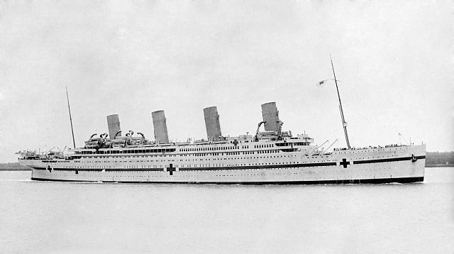
Hospital Ships became a standard in WW1, not to care for sailors, but ground troops wounded at the front, in places lacking rear facilities like in the Dardanelles; In WW2 the same repeated each time an amphibious operation was done, active until enough territory was in hands to create safe fied hospitals. The use of hospital ships, generalized in WW2 was repeated notably in the Korean and Vietnam wars among others. Nowadays, between rapid evacuation by helicopter and jetliners, and lower lethality of modern conflicts, they became a rarer commodity. If most navies does not have any, they at least have significant facilities in large vessels, like LHDs, usable in peacetime for natural disasters relief efforts.
Rescue Buoys
Another interesting concept, proper to WW2, was the construction and deployment of rescue buoys. They were deployed in 1940 (about 100 were made by Germany to save their pilots) at the occasion of the Battle of Britain, in which many pilots of both sides were downed at sea. Each plane at the time, depending of its size, was equipped with some safety equipments. Pilots were given inflatable swim jackets, and some planes had a compartment with a small rubber inflatable boat and some basic ration/safety kit. The channel was not very large, but still current were very strong and it was a feat for any downed airman to manage to get on shore.
But the luftwaffe’s losses soon urged, in addition to the old Heinkel 59 floatplanes used to rescue them, and sorties of R-Boats and S-Boats, a more permanent solution: Small shelters for four men, painted in yellow with red crosses, and a mast with a signal, and equipments and supplies for long stays until rescue arrived. Nicknamed the “lobster pods”, a few were also, ocasionally boarded by downed British pilots, or rescue boats when spotting one would inevitably check for these and captured pilots as POWs. On the British side, the task of spotting and rescuing pilots was the task of the RAF marine branch, fully separated by the RN and operate small SAR fast boats. But these unit was underfunded and strtched thin in operation. It was assumed that the numerous armed trawlers patrolling the area would provide enough coverage, but it was far from the case.
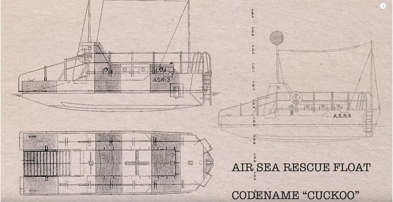
By late 1940 it was estimated that 80% of downed pilots would never be recovered, twice as much than on land. A meeting was held in early 1941 with Arthur “Bomber” Harris, at the head of the RAF, and the RN offered its service but the RAF declined and created the air sea recue service, which would increase several folds due to the ongoing battle of the atlantic and numerous convoys, in the Mediterranean and north sea route towards Russia. Soon were built 16 ASR-1, in part copied on the German models but improved in many ways. They could house six airmen, were more marine in shape with a bow and ster, and the anchor cable could be dropped in case they needed to move, but they had no engine. They had all equipments however to survive 15 days and more, a stove, rations, blankets, signalling equipments and radio. It was 32 feet long versus the German recue buoy, 13 feet long and really no more than an upscaled buoy.
The German models were ballasted with concrete in the bottom to help their stability but still, they bobbed in and out of the water and rocked considerably, so the stay was not all fun and games. The ASR-1 models, quickly dubbed “Cuckoo” were built by Carrier Engineering Co. in Wembley, ASR-1 to 16. They had ladders and railings to hang on, but the entry was at the back, a well sloped type one with a long and large wooden ladder to help exhausted men to climb more easily on board. The access was protected by a “cabin” aft. (10.8 tons, 32′ x 10′ x 3’3 feets) all steel welded 1/4 in thick. Their locations was carefully reported and four were lost (unknown causes) probably breaking their mooring during a storm and collapsed in October-November 1941 the last at unknown date and causes. They were also called “32ft feet rescue floats” in the RAF inventory. Some, listed beyond ASR-16 were all German captured buoys.
ASRs were removed soon after the end of WW2 (or even before) as they cause a danger to shipping, especially along the busy channel. Perhaps 2-3 were converted as targets, the others were simply scrapped. ASR-10 in Dover was converted into a yacht after being preserved in the 1980s. It was left stranded and restored later by the Scottish Maritime Museum, to its original state. It is on diusplay today there in its original colors, yellow and red. It was strongly built with massive mooring points to be easily towed in place. A german recue buoy also survived in the Netherlands, but in a poor state, out in the open for many decades. It was partially reconstructed by private owners.
This youtube doc by Calum says ot all.
Airbone rescue Boats
(To come)
Navigation, Communication, Detection and fire control
Long-views and Goggles
(to come)
Compass
(to come)
Maps and Charts
(to come)
Morse Projectors
(to come)
Wireless Telegraphy
(to come)
Radio
(to come)
Radars
IJN ship radars
2 Gô 1 Gata 1 Kai Shipboard air search radar
Wavelength: 1.5m
Frequency: 200 MHz (in operation this varied from 187 – 214 MHz)
PRF: 1000 (varying in use from 750 to 1500)
Pulse length: 3 – 20 µsec
Peak power: 5kw
DRange: 1 – 2 km
DBearing: 20°
Antenna type: Mattress 6 Gata antenna
Beam dimensions: 34° x 60°
Production: units
Development: August 1942
Performance: Group of aircraft 100 km, single aircraft 50 km, surface search 18km.
Notes: Development of the 1 Gô 2 Gata Dentan land based radar. Installed on many major fleet units from August 1942 onward.
Wavelength: 1.5m
Frequency: 200 MHz (in operation this varied from 187 – 214 MHz)
PRF: 1000 (varying in use from 750 to 1500)
Pulse length: 3 – 20 µsec
Peak power: 5 kW
DRange: 1 – 2 km
DBearing:
Antenna type: Mattress 6 Gata antenna
Beam dimensions: 34° x 60°
Production: units
Development: April 1943
Performance: Group of aircraft 100 km, single aircraft 50 km, surface search 18km.
2 Gô 1 Gata 3 Kai Shipboard air search radar
Wavelength: 1.5m
Frequency: 200 MHz (in operation this varied from 187 – 214 MHz)
PRF: 1000 (varying in use from 750 to 1500)
Pulse length: 3 – 20 µsec
Peak power: 30 kW
DRange: 1 – 2 km
DBearing: 20°
Antenna type: Mattress 7 Gata
Beam dimensions: 34° x 60°
Production: 2 units
Development: Experimental August 1943 to February 1944. Unsatisfactory performance all research ended by April 1944.
Performance: Group of aircraft 100 km, single aircraft 50 km, surface search 18km.
Notes: Experimental development of the 21 Gô Dentan for surface gunnery. Fitted to Nachi and Yamato. Used the 7 Gata antenna with boosted power. Performance was insufficiently good to use as a fire control set. Discontinued in development. Replaced by the 22 Gô Dentan 4 Kai S.
2 Gô 1 Gata 4 Kai Shipboard air search / surface search radar
Wavelength: 1.5m
Frequency: 200 MHz (in operation this varied from 187 – 214 MHz)
PRF: 1000 (varying in use from 750 to 1500)
Pulse length: 3 – 20 µsec
Peak power: 30 kW
DRange: 1 – 2 km
DBearing: 20°
Antenna type: Mattress 7 Gata
Beam dimensions: 34° x 60°
Production: 1 unit
Development: Experimental. Follow on to the 21 Gô Dentan 4 Kai. February 44 to May 44 when development ended. Unsatisfactory performance.
Performance: Group of aircraft 100 km, single aircraft 50 km, surface search 18km.
Notes: Experimental development of the 21 Gô Dentan for surface gunnery.
2 Gô 1 Gata 5 Kai Shipboard air search / surface search radar
Wavelength: 1.5m
Frequency: 200 MHz (in operation this varied from 187 – 214 MHz)
PRF: 1000 (varying in use from 750 to 1500)
Pulse length: 3 – 20 µsec
Peak power: 30 kW
DRange: 1 – 2 km
DBearing: 20°
Antenna type: Mattress 7 Gata
Beam dimensions: 34° x 60°
Production: 1 unit
Development: Experimental February 44 to Sept 44. Unsatisfactory performance all research ended by October 1944.
Performance: Group of aircraft 100 km, single aircraft 50 km, surface search 18km.
Notes: Experimental development of the 21 Gô Dentan for surface gunnery. Fitted on the cruiser Kiso. Used the 7 Gata antenna with boosted power.
2 Gô 2 Gata 1 Kai Shipboard surface search radar
Wavelength: 10 cm
Frequency: 3 GHz (varying in service between 2.8 – 3.125 GHz)
PRF: 2500
Pulse length: 2 – 10 µsec
Peak power: 0.5kw
DRange: 700 m
DBearing: 2 – 5°
Antenna type: Double horn antenna
Beam dimensions: 38° conical
Production: Few
Development: Early 1942
Performance Surface search 22km. .
Notes: A total of approximately 400 22 Gô Dentan Kai 1 – 3 models were produced. The 1 Kai model suffered from lack of power and remained experimental. Replaced in service by the 22 Gô 2 Kai with boosted power.
2 Gô 2 Gata 2 Kai Shipboard surface search radar
Wavelength: 10 cm
Frequency: 3 GHz (varying in service between 2.8 – 3.125 GHz)
PRF: 2500
Pulse length: 2 – 10 µsec
Peak power: 2 kW
DRange: 700 m
DBearing: 2 – 5°
Antenna type: Double horn antenna
Beam dimensions: 38° conical
Production: Approximately 100 units
Development: June 1942 to December 1942
Performance Surface search 22km. Detection of large ships 35 km
Notes:
2 Gô 2 Gata 3 Kai Shipboard surface search radar
Wavelength: 10 cm
Frequency: 3 GHz (varying in service between 2.8 – 3.125 GHz)
PRF: 2500
Pulse length: 2 – 10 µsec
Peak power: 2 kW
DRange: 700 m
DBearing: 2 – 5°
Beam dimensions: 38° conical
Antenna type: Double horn antenna
Production: Approximately 200 units
Development: October 1942 to June 1943
Performance Surface search 22km. Detection of large ships 35 km
Notes:
2 Gô 2 Gata 4 Kai M Shipboard surface search radar
Wavelength: 10 cm
Frequency: 3 GHz (varying in service between 2.8 – 3.125 GHz)
PRF: 2500
Pulse length: 2 – 10 µsec
Peak power: 2 kW
DRange: 700 m
DBearing:
Antenna type: Mattress 6 Gata antenna
Beam dimensions:
Production: units
Development: December 1942 to December 1943
Performance Surface search 22km. Detection of large ships 35 km
Notes: Experimental development to produce a fire control radar. Unsuccessful.
2 Gô 2 Gata 4 Kai S Shipboard surface search and fire control radar
Wavelength: 10 cm
Frequency: 3 GHz
PRF: 2500
Pulse length: 2 – 10 µsec
Peak power: 2 kW
DRange: 100 m
DBearing: 0.5 to 1°
Antenna type: Double horn antenna. Diameter enlarged to 80 cm on receiving horn.
Beam dimensions: 38° conical
Production:
Development: December 1943 to July 1944
Performance Surface search 22km. Large units detected up to 35 km.
Notes: First successful fire control radar. Installed late war on most major fleet units. Used super heterodyne receiver replacing previous auto heterodyne unit. Voltage stabilization was provided. Service issue began in August 1944.
2 Gô 3 Gata Shipboard surface search radar
Wavelength: 58 cm
Frequency:
PRF:
Pulse length: µsec
Peak power: 5 kW
DRange: 50 m
DBearing: 1°
Antenna type: 2 x 1.7 m parabolas (1 transmit, 1 receive).
Production: 1 or 2 units
Development: October 1943 to March 44
Performance Surface search 13 km. Detection of large ships 30 km
Notes: Japanese development of the German Würzburg radar. Experimental. Development ended in March 1944.
2 Gô 4 Gata Shipboard surface search radar
Wavelength: 28 cm
Frequency:
PRF:
Pulse length:
Peak power: 5 kW
DRange:
DBearing:
Antenna type:
Beam dimensions:
Production:
Development: Early 1944 to April 45 when research stopped.
Performance:
Notes: A development of the 2 Gô 3 Gata with shortened wavelength. Experimental only.
Japanese ESM sets
Officially known as Denpa Tansakuki.
Kai 3 Metric wavelength ESM receiver
Detection range: 75 cm – 4 m
Detection frequency bandwidth:
Detection range: 300 km
Production:
Development: From early 1943. In service June 1943.
Notes: Used 2 “Metox” type non-directional antennas plus one “tennis racket” directional antenna. The two non-directional antennas were placed on the bridge wings of the ship while the rotating directional antenna was amidships. Manufacturer’s designation: E-27
3 Gata Centimetric wavelength ESM receiver
Detection range: 3 – 75 cm
Detection frequency bandwidth:
Detection range:
Production:
Development: From late 1943. In service January 1944.
Notes: Used the 49 Gô 4.5 cm parabolic dish antenna. Super heterodyne receiver.
Source: https://www.secretprojects.co.uk/threads/japanese-radar-type-designation-systems.37818/
Bibliography
Friedman, Norman Naval Radar, Conway Maritime Press, London, 1981
Nakajima, Dr. S. The History of Japanese Radar Development to 1945 in Radar Development to 1945, Russell Burns ed., Peter Peregrinus, London, 1988.
Price, Alfred The history of US Electronic Warfare, vol. 1, The Association of Old Crows, 1984
http://pwencycl.kgbudge.com/R/a/Radar.htm
http://www.combinedfleet.com/radar.htm
https://emmasplanes.com/wp-content/uploads/A-short-survey-of-japanese-radar-Volume-1.pdf
https://weaponsandwarfare.com/2015/09/11/japanese-radar-1943-1944-i/
Sonars
(to come)
Ballistic computers
(to come)
Rangefinders
(to come)
Projectors
(to come)
Naval-related Vehicles
Naval Drones
(to come)
Naval helicopters
(to come)
Naval aviation
(to come)
Amphibious vehicles
(to come)
Hovercrafts
(to come)
Wing in ground vehicles
(to come)
Hydropters
(to come)
 Latest Facebook Entry -
  X(Tweeter) Naval Encyclopedia's deck archive
 Instagram (@navalencyc)


 French Navy
 Royal Navy
 Russian Navy
 Armada Espanola
 Austrian Navy
 K.u.K. Kriegsmarine
 Dansk Marine
 Nautiko Hellenon
 Koninklije Marine 1870
 Marinha do Brasil
 Osmanlı Donanması
 Marina Do Peru
 Marinha do Portugal
 Regia Marina 1870
 Nihhon Kaigun 1870
 Preußische Marine 1870
 Russkiy Flot 1870
 Svenska marinen
 Søværnet
 Union Navy
 Confederate Navy
 Armada de Argentina
 Imperial Chinese Navy
 Marinha do Portugal
 Mexico
 Kaiserliche Marine
 1898 US Navy
 Sovietskiy Flot
 Royal Canadian Navy
 Royal Australian Navy
 RNZN Fleet
 Chinese Navy 1937
 Kriegsmarine
 Chilean Navy
 Danish Navy
 Finnish Navy
 Hellenic Navy
 Polish Navy
 Romanian Navy
 Turkish Navy
 Royal Yugoslav Navy
 Royal Thai Navy
 Minor Navies
 Albania
 Austria
 Belgium
 Columbia
 Costa Rica
 Cuba
Cuba Czechoslovakia
 Dominican Republic
 Haiti
Haiti Hungary
 Honduras
 Estonia
 Iceland
 Eire
Eire Equador
 Iran
Iran Iraq
Iraq Latvia
 Liberia
 Lithuania
 Mandchukuo
 Morocco
 Nicaragua
 Persia
 San Salvador
 Sarawak
 Uruguay
 Venezuela
 Zanzibar
 Warsaw Pact Navies
 Bulgaria
 Hungary

 Bundesmarine
 Dutch Navy
 Hellenic Navy
 Marina Militare
 Yugoslav Navy
 Chinese Navy
 Indian Navy
 Indonesian Navy
 JMSDF
JMSDF North Korean Navy
 Pakistani Navy
 Philippines Navy
 ROKN
ROKN Rep. of Singapore Navy
 Taiwanese Navy
 IDF Navy
 Saudi Navy
 Royal New Zealand Navy
 Egyptian Navy
 South African Navy


 Ukrainian Navy