USS Spuyten Duyvil (1864)
The first USN Torpedo Boat
After suffering against Confederate use of the torpedo, the Union decided to create a ship using the same weapon. This resulted in the creation of a very original vessel, at first called the USS Stromboli, and soon renamed Spuyten Duyvil. It became in essence the first United States Navy torpedo boat, to the meaning a “torpedo” had at the time: An explosive charge brought on target by a spar, not an autonomous device.
Context: The successful confederate use of “torpedoes”
Outside the sneaky “coal torpedo” invented by Confederate Captain Thomas E. Coutenay to damage Union ships boilers, the “fixed ones” were mines, and the “active” torpedoes were spar ones, brought to bear by a ship. E. C. Singer, private engineer in charge of the “secret project” branch of the Confederate States of America created a simple explosive device using like a pistol, a trigger mechanism, adapted from a rifle lock. This spring-loaded trigger was actioned by using a long cord along the spar, which carried the device until it reached the enemy ship’s flank.
The carrier vessel was generally an ad-hoc fast and small steamer, which was to be rammed on target, embedding the barbed torpedo into the hull before backing off, the trigger cord being longer than the spar for safety. Others were just exploded on contact, with great risks to the sailors that manned the vessel. There were also proto-mines, also called “torpedo” such as those designed by General Gabriel J. Rains (director of the Confederate Torpedo Bureau) which wrote a manual, the “torpedo book”, for the fabrication and use of land mines and water mines.
The most successful “fixed torpedo”, arguably, was the “frame torpedo”, which capitalized on earlier works, dating back to the war of 1813, from David Bushnell, Robert Fulton, and Samuel Colt. After Rains, the other brainchild of the mine offensive was Confederate Navy Commander Matthew F. Maury, creator of electric underwater mines using a shore-activated waterproof cable. His device used three 400-pound, 15-inch artillery shells, cast with thin upper surfaces, and using a gunpowder fuse made dissolved in alcohol, screwed into an opening at the shell’s nose. The enemy vessel’s hull would then pressure it, crushing a thin copper protect cap leading to an explosive combination of chemicals to activate, and then ignite the fuse and blowing up 27 pounds of gunpowder.
Rains perfected the mixture, with 50% potassium chlorate, 30% sulphuret of antimony, 20% pulverized glass. These live shells were mounted to timbers, attached to large wooden frames anchored in rows to the bottom of the waterway with heavy stones. This system did not took tides and motion in account, but was raised or lowered by simply modifying the amount of weight. They were placed in harbors and across rivers and bays and found success at several occasions, sinking in all some 27 Union vessels and crippling many others. The most dramatic and spectacular was the rapid sinking of the ironclad USS Tecumseh at the Battle of Mobile Bay, which late made Admiral David Farragut famously say: “Damn the torpedoes! Four bells. Captain, go ahead!”.
One such and probably most famous use was in April 1864, when the Confederate torpedo boat CSS Squib badly damaged USS Minnesota. Before that, in 1863, the Confederates created their own dedicate spare-torpedo boat, the famous CSS David. Her first use was on the night of October 5, 1863, commanded by Lieutenant William T. Glassell, CSN, detonating gher “infernal engine” on the flank of the casemate ironclad steamer USS New Ironsides. She would also attack USS Memphis in the North Edisto River and on April 18, 1864 ried to sink the screw frigate USS Wabash. Her fate is uncertain, but she certainly impressed the Union. Later, the Confederate would go even further in furtivity, by creating their first true, all-metal submerged spar torpedo boat, the infamous HL Hunley which managed to sink the USS Housatonic on February, 17, 1864.
Design of the Stromboli


All this, and rumors for more agressive uses urged the Union to consider either an answer, which could only be done by having extra lookouts by night in particular, by default of having to armor all blockading vessels. But the Union naval officers were willing to test the spar torpedo vessel idea by themselves. Stromboli was designed by Chief Engineer of the Union Navy, Captain William W. Wood.
Hull Construction
The Stromboli was constructed of timber. The deck, sides around the water line however were covered with 1 inch (25 mm). The upper section, above water, was turle-shaped, with a 1/4 ratio (84 ft 2 in or 25.65 m long, 20 ft 8 in or 6.30 m in beam). The bow was pointy, with an opening system (see later) and the stern, rounded, but not symmetrical, as the forward part was a bit beamer, with finer lines aft.
To not give any valuable targets to the enemy, the deck was bare, with little superstructures. There was a funnel aft, and a pilothouse placed just a little ahead of the middle of the vessel, 5 ft (1.5 m) in diameter outside. It was 2 ft 8 in (810 mm) above the deck and surrounded by no less than twelve layers of iron plates 1 in (25 mm) each in thickness for a total weight of 25,000 lb (11,000 kg). This was perhaps the first conning tower. The lowe hull was deep to accomodate the machinery aft and complex torpeod reloading system forward, with little space in between. Although there was little freeboard, the Stromboli was a semi-surbmerged type design, to present as little target to the enemy when immerged, and designed for riverine warfare, with a flat-bottom and relatively shallow draft or just 20 ft 8 in (2.29 m).
Powerplant
Propulsion relied on a single four-bladed screw. The steam engine was constructed at Mystic, CT, by Mallory and Co. This simple screan steamer, one cyclinder, provided enough power to steam at 9 knots or 9 miles per hour (up to 14 km/h) down to 5 knots (9.3 km/h; 5.8 mph) when fully immersed to the gunwale, of even down to 4 miles per hour (6 km/h). The steam engine was chosen because of its smooth assembly, making it noiseless, curcial for noght operations. The Stromboli carried 160 tons of coal, enough for eight days.
Submersion system
Pumps were installed, used for filling and emptying compartments and manage the the degree of immersion. It rested on two Andrews’s centrifugal pumps “No. 6.” situated ahead of the pilothouse; They were each driven by a small oscillating engine. Their crankshaft was coupled directly to the pump’s shaft. One of these, on the port side, had its suction pipes able to draw from the reservoir or tank forward, where the torpedo loading system was placed. Her draft, fully loaded, was down to 7 ft 5½ in (2.27 m), and increased by pumping to 9 ft 1 in (2.8 m) for attack. She displaced 207 tons in this conditions, much less in reality, pumped dry and unloaded, probably around 120-130 tons.
The Torpedo System
The main and most impressive feature of the ship was of course its torpedo dispenser and reloading system. The term “torpedo” of course referred at the time to all possible explosive water devices. Today it would have been divided between depht charges, mines, and the proper self-driving “topedoes”. At the time, this was nothing more than a mine, with a retarded fuse and, brought at the end of a spar on the target.
This simple spar deliver system was managed by a torpedo-laying machinery designed by Captain Wood. It was constructed by the Clute Brothers, Schenectady, NY. This system weighted 10 tons, for only 2½ tons for her propelling engines. One of the key systems was the lower part bow composed of two iron flaps. Each hinged at the top to fire, and otherwise, kept down in place by chains attached on their lower edges through a pair of hawsepipes.
The chains were further secured to an iron rod passing into the vessel through stuffing-boxes tat the end of the hawsepipes lef over guide pulleys an drive by a hand winch. This was the “torpedo port” of the design, well before was invented the torpedo tubes. Behind the port was a tube enclosed in its own compartment, the sluice valve, and a bulkhead to be waterproof and separate of the reload mechanism.
The sluice valve slides vertically, raised and lowered thanks to a manually handled screw. When the sluice valve is opened, it admits water into an iron reservoir 6 ft 2 in (1.9 m) long, 4 ft (1.2 m) deep, and about 2 ft 3 in or 3 ft (690 to 910 mm) wide. On top of it was a manhole fitted with a hinged cover, fastened to be removed and replaced with ease. In the lower part of this tank, a suction pipe was connected to one of the Andrews’s pumps. At the other end was a gunmetal sphere 18 in (460 mm) in diameter held by two flanges to create a ball-and-socket joint.
The proper torpedo tube went through this gunmetal sphere to project the torpedoes. That projecting tube was 20 ft (6.1 m) long, 5 in (127 mm) in diameter externally, 3 in (76 mm) internally, manufactured by Morris, Tasker and Co. in Philadelphia. Each torpedo ends with a knob, button-shaped projection, so when placed in the casin, the knob is clipped by fingers carried at the end of a tubular rod, slidinh through the main tube, helding it in place until fired.
Within the spherical joint, there was a guide tube with some elevation upon side trunnions supported by bearings in vertical guides, though a a guide pulley on top of the bearing guide, trough a rocking-shaft arm placed close to the floor. It was done by a chain aft to the piston rod, in an horizontal steam cylinder fitted with slide valve, through which the steam is admitted or released driving up and back the piston, activating the chains and this the guide tube elevation.
The machinery projection/withdrawing system used two chain drums diven by a Root Company (NY) rotary engine. On is placed in the tank at the bow, used for hauling in the tube. It is also stopped by a block moved transversely along the drum while the chain is going through regular coils, a transversal motion managed by a screwed spindle gearing into a spur wheel. Hauling out of the torpedo carrier had another chain arrangement. The drums could be connected by clutches, using levers. The tube could be run in and aout at a rate of 8-12 double strokes per minute.
The reloading sequence starts with firing the torpedo, by opening the two bow flaps, rasing the sluice, projecting the tube, and the torpedo is thrust from the case at the end of the tube using a tubular rod. Once detached, the main tube is withdrawn (see the torpedo part later). The sluice is then closed, the tank is pumped dry by the centrifugal pump, the manhole is opened and accessed to use the torpedo holder. The process last for four seconds, but the reloading of the tprpedo by chains is a longer process. The total reloading time on average, is three minutes.
The Torpedo
USS Stromboli’s “Torpedoes” contained 400 lb (180 kg) of black powder, but the real detonator contained 60 lb (27 kg) of fine powder known as the one contained in Union Ordnance No. 7. “obstruction shells”. They each an air filled space managed around the powder to allow free expansion of gases. When released from the holder, they rise until coming against the bottom of the vessel and floats nearly upright while point downwards. Within the torpedo case a tube ended by a percussion fuse is ingiting the powder.
A ball is falling upon the percussion fuse, by a sliding pin placed beneath it which went through the torpedo case with a cord attached to the eye of the pin, regulated according to the desire detonation distance, on average 20 ft (6 m). When the tube is drawn back the cord is tightened, releasing the ball to the percussion fuse; which detonate the fne powder, and by extention, the rest of the charge; The explosion, under the ship’s belly, was supposed to break it’s back…
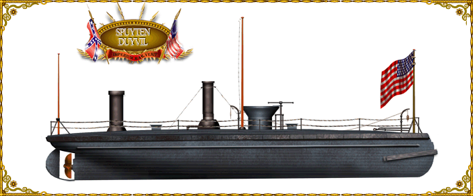
Author’s illustration of USS Spuyten Duyvil
Specifications |
|
| Dimensions | 84 x 20 x 7 ft (25,65 x 6.3 x 2.29 m). |
| Displacement | 207 t. standard, 210 t. FL |
| Crew | 23 |
| Propulsion | 1 shaft steam osc. engine, 1 boiler ?KW |
| Speed | Top speed 5 kts (9 mph, 14 kph) |
| Range | Unknown but 160 tons coal |
| Armament | 1 spar torpedo |
| Armor | Pilothouse: 12 in (300 mm), Hull: 5 in (130 mm), Deck: 3 in (76 mm) |
Construction and career

When ordered in mid-1864, task was to find a suitable constructor. Samuel M. Pook at New Haven, Connecticut, was eventually chosen by Wood, which supervised her construction step by step. Ccontract for her construction was dated 1 June 1864. Construction started probably in July, however launch is generally attributed by default to September, but there are no confirmed records for both her launching and commission. Period records indicate that she was completed in just three months, and her first tests started in November, suggesting tests started before even she was considered “completed” in the conventional manner.
It is likely she was able to perform sea trials already in November, just one month after launch. Granted, her fitting out did not required a lot. The most complicated part was of course to get her complicated torpedo reload system to work properly and the crew to train enough on it to be ready for action.
On 19 November 1864, she was renamed “Spuyten Duyvil” after the Bronx neighborhood. On 25 November 1864, she made its first successful “torpedo” launches. Later that month, Commodore Charles Stewart Boggs took command. She was to be towed by Picket Boat No. 6, plus the steam tug “John T. Jenkins” to Hampton Roads in Virginia. She stopped in on 2 December while Boggs turned both Spuyten and the picket boat to Commodore T. A. Dornin. Both vessels were now placed under the care of First Assistant Engineer John L. Lay, for the remainder of their trip. They arrived both in Norfolk on 5 December, prepped for thei final leg of their mission.
Spuyten Duyvil was ordered up the James River on the 14th, in order to help the Union controlling this river and support General Ulysses S. Grant’s offensive on Richmond. She presented herself off Akin’s Landing, on 15 December 1864, to enter the upper James river just below the Confederate obstructions, trying to blast them up. This went on for monthes on end.
During the night of 23/24 January 1865, the Confederacy’s James River Squadron a resolute assault on the Union squadron composed of various steamers, mostly unarmoured, an episode known as the Battle of Trent’s Reach. USS Spuyten Duyvil supported the monitor USS Onondaga, the centerpiece of the Union fleet.

General Robert E. Lee eventually evacuated Richmond, so Spuyten Duyvil was able to blast the remaining obstructions in the river, until then protected by Confederate batteries, now evacuated. This make it possible latter for President Abraham Lincoln to steam up the James river up to Malvern and after its carrier ship ran aground, he was rowed to safety close to Richmond. Her demolition role did not stopped with the end of the war, in April. Exactly like after WWI and WW2 she played a mine-clearing role for a solid year afterwards James.
When her mission ended, she returned to the New York Navy Yard, placed in ordinary (reduced crew), in 1866. Technically decommissioned, but she went on being used for more experiments, gradually improved for the remainder of the 1860s and 1870s, until was written off from the Navy list only in 1880.
❢ Note: Technical explanations were shortened and simplified. They are far more expanded in the original texts, now in open source and associated with the blueprints, found at the Naval History and Heritage Command website.
Src/read more
On civilwartalk.com
On history.navy.mil
navalunderseamuseum.org
wiki about spar torpedoes
CSS Torpedoes on opinionator.blogs.nytimes.com
About confederate mines, Gabriel J. Rains (Author), Peter S. Michie (Author), Herbert M. Schiller (Editor)
Model kit on civilwarnavy.com
On 209 foundation
Construction photo on loc.gov/
On scalemates
On myinwood.net
archives
On laststandonzombieisland.com/


 Union Navy
 Latest Facebook Entry -
  X(Tweeter) Naval Encyclopedia's deck archive
 Instagram (@navalencyc)

 French Navy
 Royal Navy
 Russian Navy
 Armada Espanola
 Austrian Navy
 K.u.K. Kriegsmarine
 Dansk Marine
 Nautiko Hellenon
 Koninklije Marine 1870
 Marinha do Brasil
 Osmanlı Donanması
 Marina Do Peru
 Marinha do Portugal
 Regia Marina 1870
 Nihhon Kaigun 1870
 Preußische Marine 1870
 Russkiy Flot 1870
 Svenska marinen
 Søværnet
 Union Navy
 Confederate Navy
 Armada de Argentina
 Imperial Chinese Navy
 Marinha do Portugal
 Mexico
 Kaiserliche Marine
 1898 US Navy
 Sovietskiy Flot
 Royal Canadian Navy
 Royal Australian Navy
 RNZN Fleet
 Chinese Navy 1937
 Kriegsmarine
 Chilean Navy
 Danish Navy
 Finnish Navy
 Hellenic Navy
 Polish Navy
 Romanian Navy
 Turkish Navy
 Royal Yugoslav Navy
 Royal Thai Navy
 Minor Navies
 Albania
 Austria
 Belgium
 Columbia
 Costa Rica
 Cuba
Cuba Czechoslovakia
 Dominican Republic
 Haiti
Haiti Hungary
 Honduras
 Estonia
 Iceland
 Eire
Eire Equador
 Iran
Iran Iraq
Iraq Latvia
 Liberia
 Lithuania
 Mandchukuo
 Morocco
 Nicaragua
 Persia
 San Salvador
 Sarawak
 Uruguay
 Venezuela
 Zanzibar
 Warsaw Pact Navies
 Bulgaria
 Hungary

 Bundesmarine
 Dutch Navy
 Hellenic Navy
 Marina Militare
 Yugoslav Navy
 Chinese Navy
 Indian Navy
 Indonesian Navy
 JMSDF
JMSDF North Korean Navy
 Pakistani Navy
 Philippines Navy
 ROKN
ROKN Rep. of Singapore Navy
 Taiwanese Navy
 IDF Navy
 Saudi Navy
 Royal New Zealand Navy
 Egyptian Navy
 South African Navy


 Ukrainian Navy
 dbodesign