
Naval Artillery – All types, caliber and timeframe
I considered important, in complement to the subject matter of this wesbite – warships – to have a look more in detail about their primary payload and the way it evolved and created new tactics. It seems obvious at first glance, when looking at the ful picture of 2,000 years of naval warfare, that we went basically from a “close and personal” affair to a “press-button” one, at greater and greater distances. Today a nation equipped with a dozen of hypersonic missiles -for which there is no cure at the moment- could wipe out one or several task forces and nullify a naval power overnight. And the button pressed could be either in side a compunded under the Kremlin, in Peking or Washington, with none in the assembly having a clue of the faces of those they are going to send down many fathoms.
That’s the nature of war today, cold and totally impersonal, made of statistics and data fusion.
Thus, there was a time it was all different. As soon as mankind mastered a way to get on water, either a raft or dugout, fights erupted with anything available on hands, clubs, stones and javelins.
Constituted fleets in the Bronze age and classical greece, the Median wars, saw advances in “long ship” notably with the invention of the trireme, but still not naval artillery, which was only introduced as ships weht bigger, in the hellenistic era. Although ramming and boarding were still playing the largest part of the fighting, these heavy early ranged weapons, catapults and ballistae to sumplify, played their part in various ways (see later).
There was no much change until the fall of the Hellenistic Empire, the fall of the Roman Empire and early middle age, and in turn, the fall of the Byzantine Empire, which at least saw coming from the east a formidable new invention, gunpowder.
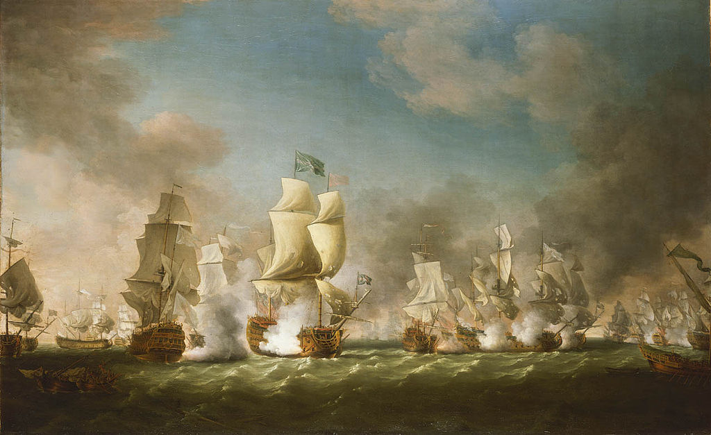
The battle of Cape Passaro
Cannons made their way slowly into ships in the XVth century, before further developments made it central to new tactics, in the following centuries and up to the 1860s. For 400 years indeed, ships were now fighting in line, blasting at each others with more and more refined cannons and at greater distances. But boarding actions were still the norm. However it’s only with the industrial revolution that better casting techniques broughts new rifled, breech-loading guns, revolving platforms and finally turrets, meaning ships, which also got armour protection, and transitioned to steam power in the last decades of the XIXth century, increased the fighting distances to dozens of miles and made a boarding action totally irrelevant.
The science of explosives led to the carronade, to the shell instead of a ball, and a variety of new projectiles, some made to pierce the newly developed armour plating. Until 1906 and the HMS Dreadnought which just pushed the envelope of a relatively well fixed formula since the 1880s, there was no greater predator for a warship that itself, that is until new asymetric technologies matured:
The mine, and the torpedo (and thus the torpedo boat) and it’s underwater form, and by the end of WWI, aviation. Thus from 1920 a ship had not only to care for underwater but also aerial threats, in addition to its own kind. Still, artillery in all these cases reigned supreme. We have to wait for post-WW2 to see development of a sort of mix between a torpedo and a rocket, both far more ancient, merging into the missile. And it’s only by the 1960s that the latter became widespread, and as naval-air battles, pushed the threat well beyond the horizon. Fleets don’t needs to see each others anymore, or even leave the port. A technology incomprehensible for a 1860s captain, just 100 years or four generations before.
I hope to give in this massive, always expanding article, not only an idea of this evolution, but also the types discussed in various articles, and precised, well known artillery types frequently called when tackling most warships of WWI and especially WW2 thanks to standardization. But also the cold war, since artillery never disappeared from modern warship’s decks, neither machine-guns. And look into the future like hypervelocity projectiles and magnetic cannons, or direct energy weapons (lasers).
Lineage of ancient naval artillery:
Antique weaponry
“Artillery” is generally assimilated to gunpowder age cannons. However, the art of throwing projectiles on an enemy, beyond the usual stones and arrows of ancient times, was built up over centuries to solve the siege question. Defeating walls was already developed as an artform by the Assyians (circa 700 BC), but it’s only the Greeks which started development of two great families of siege weapons, the Katapelte (catapult) and the Ballista, supposed to clean up walled defensers. The first was developed furter in the Hellenistic era by Demetrios Poliorcete as the Onager, and the Polybolos became a smaller version, whereas the Ballista morphed into stone-throwing types, much larger.
The Bronze age saw the consolidation of city-states and the first unified fleets, instrumentalized to attack merchant traffic, blockade a port, and counter an enemy fleet. When it was done, the lack of historical evidence (rare decriptions and bas-reliefs) with unreliable graffitis depicting these early ships left us mostly clueless, but to envision a form or land warfare transported at sea. Let’s draw some believable hypothetis here:
-Early pentakonter and smaller vessels were too weak for ramming, so no fancy tactics
-Bows existed as well as slings, and javelins, so ranged battles was very likely to soften up an enemy when closing
-Rowers were not slaves and thus could take part in a possible boarding battle
-Conversely the “free space” on these long and narrow ships was too limited for a even a modest professional warrior contigent, outside ranged infantry.
Thus, as it repeated many times in history, the “rowing warriors” scheme seems the only rational one to explain the scale of these naval battles.
Now, if you followed this through, we still don’t see any naval artillery there, only the common infantry range encountered in land battles.
For this, we have to fast forward past the “classical era” of Greece, to the Hellenistic era. Here, two things happens:
-“Artillery” is created and transferred at sea
-“Decked” (Kataphraktoi) emerged. As ships became larger, they allows these on board.
Artillery has been invented thanks to mathematics and practical science applications converting torsions forces of the bow into much more complex and larger weapons able to throw heavier projectiles at larger distances and on the other hand, the katapelte (catapult) throwing much larger loads in a parabolic way.
Bows were used at least since 8,000 BC but most agrees they probably dated back around 20000 BC. The word “Catapult” from ‘kata’ and ‘peltes’. (“downward” “small shield”) or “shield piercer” was a concept invented about 400 BC in Syracus under Dionysios I (c. 432-367 BC). Greek engineers also created the gastraphetes (belly-bow), ancestor of the crossbow, essentially a large bow mounted on a case, and soon the device was enlarged with a winch pull-back system added, fixed on a base.
The “Belopoietic” (from belos ‘arrow/bolt’) became a studied part of ancient mechanics as part of the mathematics and also comprising statics and pneumatics.
Weapons fired by torsion bars, powered by horsehair and ox tendon was used to fire a large variety of “missile”, arrows, stones, and burning tar pots, along a parabolic arc. Being large and heavy unlike the one-man gastraphete, they were mounted on wheels for tactical mobility, and on deck fixtures on ships.
Here comes the Katapkraktoi.
The most important point: You need space to fit such devices onto a ship. The average trireme was about 35m long and 4m wide, but almost all this space was occupied by the rowers. For them to better support the crushing sun, they were partially covered (“hemi-aphraktoi”), with a long central “trench” opened to let air pass, in addition to the side openings. This way, this left most of this upper deck open for any purpose. That is where stability intervenes. These ships were even narrower at the waterline, with a ratio of perhaps 1/11 or 1/12, and thus, very unstable on this upper deck. Loading dozens of combatants would have simply jeopartize this stability. Only a few were required, and that’s why in battles such as Salamis, archers were used, although there was some ramming, but no artillery could be mounted on these vessels.
It was not long before adoption on Hellenistic ships, which became larger over time. The old triere had none, since it was not fully decked, there was just not enough space aboard. However the “kataphraktoi” type galleys such as the “four” or tetrere, the “five” or pentere, and above, all had full decks, and enough space for these. Polybolos and Ballistae had different purposes and projectiles; The first could throw rocks on the enemy’s rows, breaking them on a side to put them off-balance, presenting their flank for a ramming attack. Flaming pots were used to start a fire on deck. There are descriptions even of bees or snake-filled posts, but they are to be taken with a grain of salt depending on the source. Ballistae on their side, were used to clean up enemy decks, the same way as walls, before a boarding action, but it was rare in pre-roman naval warfare. Whatever the case, these ranged weapons were classed into the great families of Flexion or Torsion mechanics, firing Arrows or Stones (or assimilated projectiles like tar pots).
The Oxybele
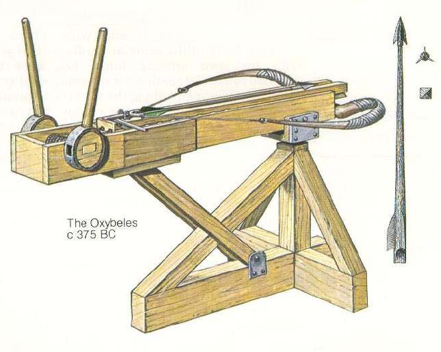
A drawing of an Oxybele circa 375 BC. A glorified, fixed Gastraphete firing heavy bolts.
The granddaddy of all these weapons are the Gastraphetes (γαστραφέτης) or “belly bow”, as the used had to press it’s breech under it’s own belly to crank it up to torsion before firing again. The torsion allowed it to fire on straighter trajectories, much greater velocity. The iron darts or arrows fire would in effect pierce any armor or helmet and it regain in punch and distance what it lacked in rate of fire. Let’s be straight here. There is no single evidence written of Gastraphetes deployed in a ship. It just made sense that it could have been used, notably to “clean up” the archres posted on top of ship’s turrets or castles as it was used in sieges.
The Gastraphete was around 15 long and could send 40 pounds at 200 to 300 yards according to Heron of Alexandria and it proved very important in the siege of Motya in Sicily, 397 BC. From there, it was obvious that scaling it up could only brings some benefits. Thus the army of Dionysius I apparently defeated the Carthaginians with an even larger version of the gastraphetes, possible out-ranging archers.
The Oxybeles (Οξυβόλος) (“bolt shooter”) was basically a larger Gastraphere fitted on a solid mount. Too large and heavy to be used the old way, a single “servant” actioned levers back and forth to crank up the whole launcher to maximal tension before release. The same benefits as the Gastraphetes, but at many more distance.
Biton, Zopyrus, or Charon of Magnesia redacted treaties in the Hellenistic era for even more refinements. Among others, king Attalus I of Pergamum (241 to 197 B.C.) created a large fleet counting many “kataphraktoi” including these kind of weapons on board. We can only illustrate their use at sea, when two fleet approached, archers would not even start before being decimated by these. The power, speed and distance was impressive enough, having a psychological egde to it. A single bolt could also crucify together two combatants, projecting them at sea or nailing them on a structure. They also can clear lookouts on top of the mast, giving valuable intel to the commander, well above the melee.
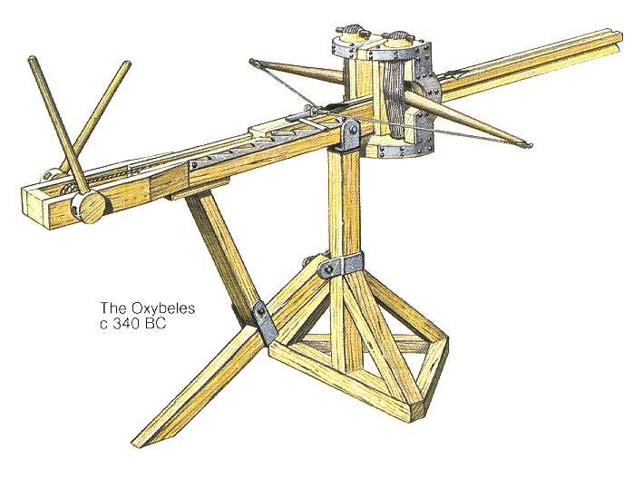
A Torsion-based Oxybele, circa 340 BC. Same base mechanism but using torsion, no longer the classic bow-type tension, rather a better adapted force for these heavy weapons, taking full advantage of their size. They still fired heavy arrows, and packed a better punch. It was the mechanic retained by the Romans for their own ballista.
The principle of torsion was probably invented in Macedonia under Philip II and Polyidus (353-341 BC) and they were used at the siege of Perinthus and Byzantium in 340 BC. Inscriptions from the Chalkothek on the Acropolis of Athens also mention torsion spring “catapults” at about 330 BC. These torsion-based Oxybeles were able to get through shield and armor at 400 meter. Most archers did not have this range, especially at sea.
It was also Philip of Macedon who first organized a specialize corps of artillery engineers. With Demetrios I “Poliorcetes” (305 B.C.) this was perfected further and probably reached the culminating point of ancient ranged artillery. Alexander the Great used them as covering artillery on land, carrying in this army prefabricated catapults of 85 pounds and larger ones carried along in wagons. The later hellenistic era and Diadochi wars also did not lacked the use of these, as sieges were a central part of this warfare, but as ships grew accordingly (with “tens”, “twenty” aplenty), and for the most massive likely twin-hulled, there was no sorthage of deck space and turrets to fit a large variety of artillery, for all purposes and range. There were two recoignised types, the Oxybele and the lighter form, called the Euthyntonon.
The Palintonon (Ballista)
Appeared around 335 BC, this was a heavier version, this time not used to throw arrows but Spherical stones (10-80 pounds). It could ba placed on a pivot mount and just counted on larger frames and torsion mechanisms to launch heavier projectiles at distances beyond 400 m. But there was a limit in size up to which the forces applied to the wooden framework were so great to reach breaking point. Hence past 50 AD, metal framing was used as reinforcement, leading to even greater strenghts and the Cheiroballista. As for massive basllistas or even Catapults and Onagers, where they of any use on a ship ?
That seems obvious. An arrow and dart would have a “sniping effect” but overall not great results on a entire ship/crew wheras heavier projectiles could have two dedicated purposes:
A rock will break rows, ensuring to slow down an enemy ship for a closer action
A tar pot, used an incendiary, would turn into an inferno any warship, without the need to board it.
The Cheiroballista
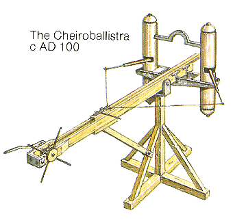
A Cheiroballista, (Roman Manuballista) with metal frames was still use to hurl arrows at large distance and probably appeared around 100 AD, invented by Apollodorus of Damascus for the Roman army. Springs are stretched in two separate metal casings with a metal stud attached the top of each of the field frames. Another stud at their bottom and base hold the spring casings in place. It became the most advanced torsion engine used by the Roman army, probably until the fall of the Empire.
The Romans of course develop these as an art form. Their catapults and onagers were used to break rows and slow down their generally nimbler, faster opponents, until ballistae were used to launch the harpago, the famous grappling hook which allowed them to catch their prey. Once close enough the corvus was used for the proper assault. The Roman army had stone-throwers capable of 27 kg over 150 meters. Archimedes was said to have machine firing three times that weight. Plutarch referred to Hiero (king of Syracuse) as suprring him into military engineering, delaying much the Roman siege of 212 B.C.
These pre-gunpower weapons stayed relevant, with minor variations, under the Byzantines, which additionally introduced flamethrowers on their Dromoni. However in the early medieval age, ships were small again, and therefore archery, especially in northern European waters was deemed sufficient. None of the land war machines like the towering trebuchet was back on a warship, but in rare and special occasions like sieges. However it’s not impossible catapults were still in some cases in naval battles, throwing greek fire pots in complement to the archers. 1
Ancient Naval Cannons
Gunpowder was brought out in Europe in the early 14th century, and was introduced on ships quite soon. At the Battle of Arnemuiden, fought between England and France in 1338 (opening of the Hundred Years’ War), “HMS” Christopher was armed with three cannon and one hand gun.
In Asia it was used in mass at the Battle of Lake Poyang in 1363 and Jinpo in 1380 on the Korean side. 80 Koryo warships repelled 500 Japanese Wokou “pirates” with cannon fire alone. The 15th saw all Mediterranean powers investing in cannons and fire arms of all sides in quantities on their large carracks: A few heavy cannon mounted on the bow or stern to bombard fortresses and the first broadside cannons from 1450 onwards. Countless others, smaller types, were mounted in fixed carriages or pintles, sometimes in the carrack’s tall “castles” fore and aft. These were anti-personnel weapons fired at point blank range with muskets or bows before a boarding action.
From the 1470s, Portuguese and Venetian navies introduced these on galleys, massed forward, and used as real anti-ship weapons. King John II of Portugal pioneered the introduction of reinforced decks on caravel to mount new long range heavy guns. These wrought iron breech-loading basilisks were slow to fire but devastating. However in the Mediterranean, lighter, more accurate bronze a muzzle loaders firing stone balls up to 60 lb (27 kg) became the norm. By 1489 John of Portugal established the first standards for the training of elite naval gunners, the bombardeiros.
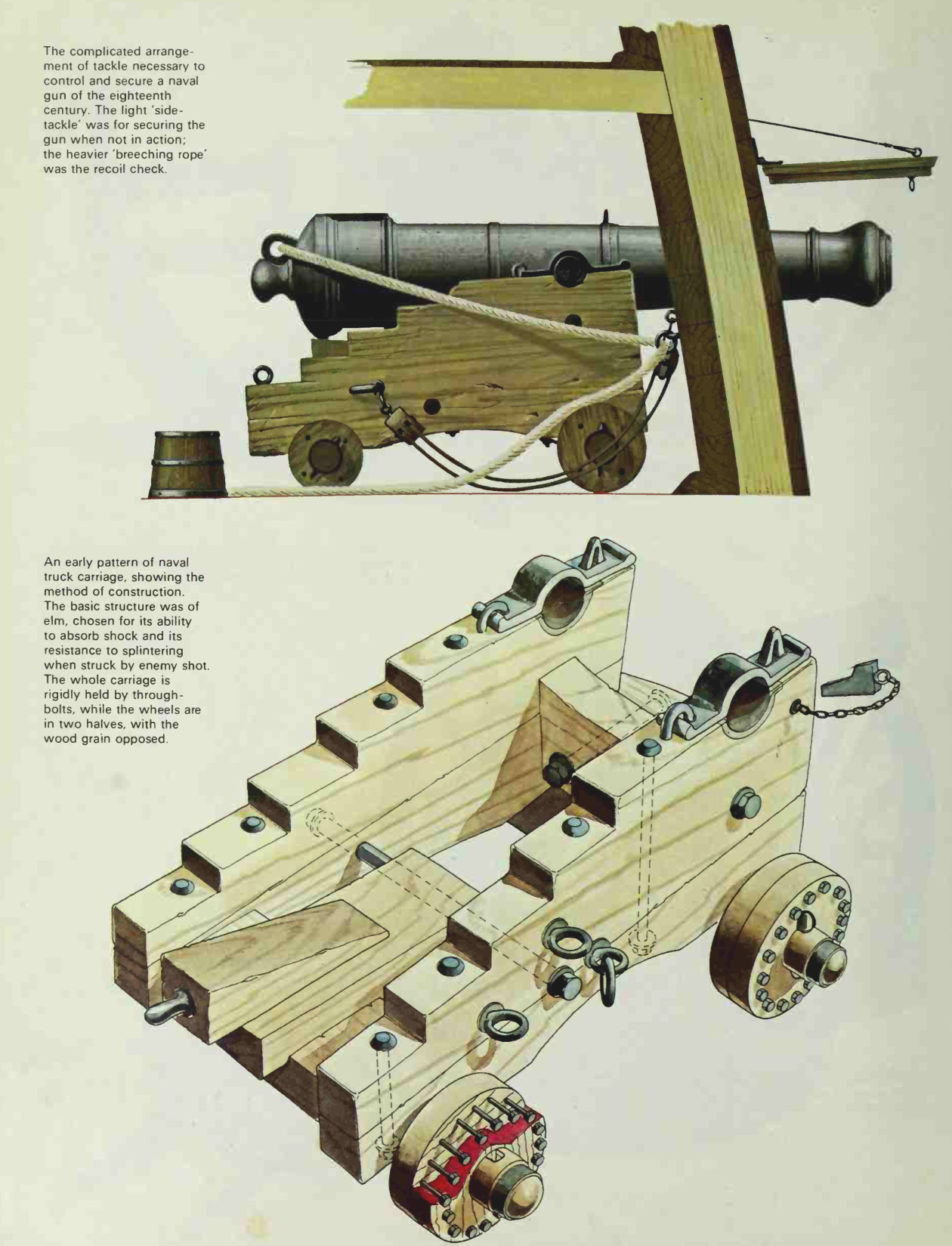
XVII-XVIIIth Cent. Naval Artillery
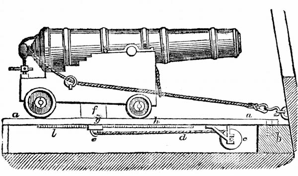
The 16th century saw a first transition in naval warfare. Bows and crossbows fired from a ship were not changed fundamentally by the gradual introduction of guns, but it soon changed the dynamics of ship-to-ship combat, as they got more reliable and powerful, then when placed lower in the ship, closer to the water line, and thus protected by the elements by the introduction of portholes.
16th-century galleys had a few broadside cannons, mostly on swivel mounts, the heavier ones being placed in the forecastle and aftercastle. Due to their short furing distances, they were merely used to deter boarders. On carracks, from their elevated castles, bows and arrows were also gradually replaced by firearms for the same purpose. Boarding was still the common tactic.
However naval artillery was pushed to such a perfection by the Portuguese that they defeated all their rivals in the Indian Ocean. Their expertise in gunnery soon earned the very peak of what European technology permitted at the time, but ot was a crown-funded industry, with sometimes volatile cost considerations and sometimes contradicted innovations and training. They took advantage of several innovation in bronze cannon foundry (Flemish/German in origin) and of breech-loading swivel-guns and English wheeled carriages and the probably invented French (. 1501) cutting square gunports, adopted as “portinhola” and introduced from 1490 systematically on all carracks. The Portuguese spearheaded this evolution towards the use of artillery to resolve battles by gunnery alone. 2 3
Industrial era Naval Artillery
The modern muzzle-loader
The carronade

(To come)
The first rifled guns
The breech-loaders
The development of modern shells
XXth Cent. Naval Artillery
Naval Guns of WWI and WW2. They brough faster fire and longer range, but between Jutland in 1916 and Leyte in 1944 the biggest change was the use of fire control radars, coupled with far more accurate computers.
QF guns
The concept of quick-firing guns, Vickers, Hotchkiss, Nordenfelt… This section is in long-term development.
Hotchkiss revolving cannon
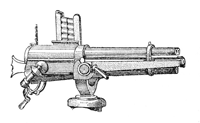
The Hotchkiss revolving cannon had a rotating barrel inspired both by the 1861 Gatling and revolver pistols of the time, but ported to a much larger caliber. It was invented in 1872 by Benjamin B. Hotchkiss (1826–1885), founder of Hotchkiss & Co. This was the first “Hotchkiss gun” and it had, to avoid pattern disputes, very different internals compared to the original from Richard Jordan Gatling. It had a single reciprocating bolt rather than separate action for every barrel, and showed built-up, rifled tubes with oil-tempered steel, rectangular breechblock moving in a mortise cut through the jacket. It was still light enough to travel with cavalry and a range suprior to most rifles.
The 1-pounder revolving Hotchkiss cannon was 37 mm in caliber, with an unprecedented 68 rounds per minute, relatively accurate still at 2,000 yards (1,800 m). It was loaded with ten-round magazines weighting 18 pounds (8 kg) each. Alonsgide the Nordenfelt guns, it became a staple of naval defense against torpedo boats, adopted by Russia, France and the United States in the 1880s. Maxim-Nordenfelt 1-pounder cannons were however ofrten preferred and used from 1880 to 1910. The British called them quick-firing (QF), the US, rapid-firing (RF).
WW2 Artillery
WW2 AA artillery
The development of anti-aircraft artillery:
The first concrete need for AA defence against aeroplanes (heavier than air) coincided with the Italo-Turkish war of 1911-1912, when planes were used: On 23 October 1911, Capitano Carlo Piazza made the first air reconnaissance over the Turkish lines. On 1st November Sottotenente Giulio Gavotti dropped bomblets on Ottoman troops in Libya from an Etrich Taube, but later in August 1912 Lieutenant Piero Manzini was shot down by rifle fire, also a first. Therefore the Italian admiralty had in mind to contemplate the possibility of an air attack on their ships and plan for essentially a modified version of an existing gun, notably with a greater elevation going up to 80°. They were not alone. The threat caused by balloons much earlier prompted both France and Germany, also too pioneers of aviation, to devise counter-measures.
The granddaddy of the famous “FLAK” guns and incidentally of all AA guns was even devised much earlier at the occasion of the 1870 Franco-Prussian war. As Paris was besieged a massive communication via balloon started, which could go with impunity over Prussian lines, that is until Gustav Krupp came up with a modified 1-pounder (37mm) gun called the Ballonabwehrkanone.

Incidentally, it’s Germany that first implemented an AA gun on a ship, here in 1872 the Corvette Nymphe.
To deal with the destruction in the air of a moving target was so daunting that a direct exploder could not work, and various ammunitions were proposed. One was a shrapnel-throwing high explosive, or incendiary (canvas and wood) or bullet-chains as well as rod bullets plus an early tracer to correct fire on the fly. Some scientists also came with an eary Fuze type. AA guns envisioned were light, on pedestals or on field platforms. Krupp, Erhardt, Vickers Maxim, and Schneider published patents by 1910, Krupp being the most prolific with adaptations of a 65 mm 9-pounder, 75 mm 12-pounder, and 105 mm gun. Erhardt proposed a 12-pounder but Vickers Maxim went to a 3-pounder, Schneider to a 47 mm, having a balloon gun operational the same year. The latter was a 11-pounder mounted on a vehicle with simple sights. It was not sufficient to deal with planes through.
WWI AA guns
1913 France and Germany integrated high-angle field guns in special units to engage either balloons and aircraft, soon followed by Britain with its QF 3-inch and a QF 4-inch AA, plus the legendary Vickers 1-pounder QF pom-pom, start of a long lineage that went straight to the cold war. In the USA, it’s the Navy that was responsible for the first AA gun, an 1-pounder designed by Admiral Twining in 1911, to be installed on ships to deal with airships, but since aicraft were just a bit faster, it turned into the basis for of the 3″/23 caliber gun, first Naval dedicated DP gun in the USN. In Britain, the same caliber by Vickers was also retained, in adition to the Vickers 0.5 in, and the 2-pdr Pompom. In Britain the latter from 1914 were often used around ports, coupled with projectors.
As WWI progressed and encounters both with airships and planes became more commonplace (but soon with almost no air naval attack yet, at least until 1918). Eventually the British Army and the RNAS started to field trucks converted as early SPAAGs by installing a 13-pdr QF 6 cwt Mk III issued in 1915, installed on their flatbed. It became quite common for all belligerents soon after.
By 1915 a Royal Navy gunnery expert, Admiral Sir Percy Scott, was appointed to improve British AA cover around London. New RNVR AA guns were used, with a much longer range than 3-in pom-poms, which were ineffective. The naval 3-inch was adopted by the army as QF 3-inch 20 cwt (76 mm) by 1916. But all ships built since 1914 had a provision of AA guns. The 3-in became a staple for the RN, as well as the 3-in/23 for the USN, the French and Japanese looking at Hotchkiss designs. The Germans trusted their goold old 8.8cm, widespread in the fleet, to receive a new high-angle mount. This was the direct ancestor of a much fiersome model in WW2.
All this time, AA gunners had to write the book and learn their trade. AA gunnery was indeed quite difficult to master, from predictive aiming, to having the shell bursting close enough and the right timing to damage it’s target taking in account many factors affecting the trajectory. The deflection gun-laying with off-set angles for range and elevation could be gathered at the gunsight and updated during the target’s evolution. When sights were on target, the barrel pointed to its future position, based on estimated speed and altitude. The latter data was required to setup the fuse length. Of course matter was made worse by higher speeds, above 200 kph.
 British AA Artillery
The first attempts as designing AA guns went back to the Boer War to deal with rare Boer observation balloons, using an adapted Vickers 3-in naval gun. Soon also the Boers starting using an early 1-pdr autocannon developed by Nordenfelt and Maxim, soon acquired by Vickers. It’s really before 1914 that ships started to received some AA artillery, generally ither the standard 3-in Vickers or the 1-pdr pompom, later turned into a 2-pdr pompom during the interwar. This became the Royal Navy standard, alongside other calibers, notably the quad tandem Vickers 0.5 in for the lower tier.
This section is in development, all types are to be covered.
Vickers QF 0.5-in Heavy Machine Guns
The Vickers .50 machine gun, also known as the ‘Vickers .50’ was just an upscaling of the famous .303 inches (7.70 mm) Vickers machine gun. For it also a larger calibre 0.5-inch (12.7 mm) round was designed, also up-scaled to fit and use the exact same mechanics. It saw use in light tanks (before replacement by the Besa) and other fighting vehicles but also became the staple of Royal Navy ship born AA, in the shape of four-gun mounting (UK) and two-gun mounting for the Dutch Navy. The .50 Vickers (12.7×81mm) was quite different and not compatible with the contemporary .50 BMG (12.7×99mm) of the ubiquitous Browning (“Ma Deuce”) M1920 Machine Gun. Far less effective than the “pom pom” it was recoignised obsolete by 1941 and started to be replaced by the 20mm Oerlikon, and later Bofors 40mm single mounts.
On HMS Vanity, V class destroyer, 1940 (IWM)
Specifications 0.5 in Vickers Quad AA
Mass: 63 pounds (29 kg) with 10 pounds (4.5 kg) of jacket’s cooling water
Total Length: 52.4 inches (1,330 mm)
Barrel length: 31 inches (790 mm)
Cartridge: 12.7×80mm
Calibre: 0.5 inches (12.7 mm)
Rate of fire: 500–600 rounds per minute
Muzzle velocity: 2,540 feet per second (770 m/s)
Maximum firing range: Altitude: 9,500 feet (2,900 m)
Range: 4,265 yards (3,900 m)
Feed system: belt
QF-2 pdr naval gun Mk.VIII
Origins
The generic QF2-pdr was one of the oldest AA gun in existence. The one used in WW2 long derived from the QF 1 pounder used in the Boer War: It was essentially derived from the 37 mm Nordenfelt-Maxim “QF 1-pounder” used in the Second Boer War as a regular artillery piece firing a 1 lb (0.45 kg) shell at 3,000 yd (1.7 mi; 2.7 km). It was singular as having a water-cooled barrel and belt-feeding, with 25-round fabric belts. This was thus an early “auto cannon” at 450 rounds per minute. But it’s the Boers that used them first against the British, which ordered them in turn from Vickers, just acquiring Maxim-Nordenfelt in 1897. In WWI it was deployed as standard AA gun with a lot of efficience.
The QF 1½ pounder was its first naval derivative, called the QF 1.5-pdr Mark I, still 37 mm (1.46 in) and 43 caliber long. Tested on HMS Arethusa and Undaunted this did noot led to its adoption but rather an up-scaled verison worked on as the QF 2-pdr Mark II.
Development of the QF 2-pdr Mk.II
The QF 2-pounder Mark II was a larger QF 1-pounder Maxim gun, made by Vickers, 40 mm in caliber and still retaining its water-cooled barrel plus Vickers-Maxim mechanism. Ordered in 1915 already by the Royal Navy it became the standard on cruisers and smaller vessels, corvettes, frigates ad gunboats. The first still used a hand-loaded fabric belt, later replaced by articulated steel-link belts which was not very sucessful. Some survived into World War II on small ships and were surplus fitted on patrol naval trawlers as well as motor boats and “armed yachts” requisitioned by the Navy. Always fitted as single-barrel with manually-traversed pedestal mountings P Mark II. A few were also found using the twin mount Mark XV fully powered, but mounted ashore. They played a dubious part in the battle of Britain and were generally retired and replaced or scrapped by 1944.
To have an idea of its potency, the 40 mm L/39 measured 96 in (2,400 mm) with a 62 in (1,600 mm) bore, and weighted with the complete mount 527 lb (239 kg). It fired 2 lb (0.91 kg) HE shells at 200 rpm up to 1,200 yd (1,100 m) at 1,920 ft/s (590 m/s). In total, some 7,000 guns were made, some ending in Japanese (40 mm/62 “HI” Shiki) and Regia Marina service. The latter replaced it gradually by the Cannone-Mitragliera da 37/54 (Breda).
40 mm Bofors cal. 56 Mark 12 ONI
The standard QF 2-pdr Mk.VII/VIII
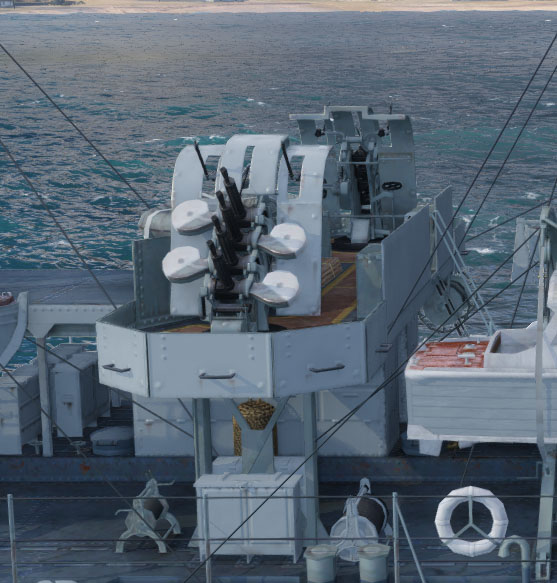
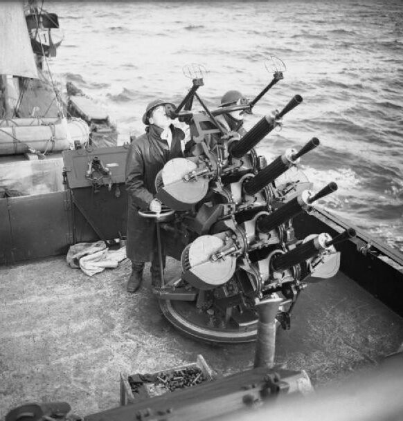
The Royal Navy tested it but preferred a more rapid-firing and multi-barrelled anti-aircraft mount, which design started in 1923, based on the Mark II and firing considerable stocks of surplus 2-pounder ammunition. However in funds-starving interwar Britain, it’s only by 1930 that this new gun entered service as the QF 2-pounder Mark VIII (“multiple pom-pom”).
The standard was initially the 11.8-17.35 ton, eight-barrelled Mark V mount, later refined as the Mark VI and generalized on all ships in the Navy where a suitable spot could be found. From 1935, it was supplemented, for tighter spaces, by the quadruple mounting Mark VII (Mark V-VI mount) notably for destroyer and light cruisers. They too, were nicknamed the “Chicago Piano”. They still were standardized and so could have two rows each of two to four guns produced in right-hand/left-hand and always in inner and outer sets so that feed and ejector mechanisms always matched.
There was a single barrel mount called Mark VIII (manual) -to complicate things- and a Mark XVI which was the same but power operated mostly for small vessels, escorts such as the Flower-class corvettes or Fairmile D motor torpedo boats.
The Mark XVI was made to match the standard twin mount Mark V made for the Oerlikon 20 mm cannon and its single-barrel “Boffin” mounting adapting the Bofors 40 mm gun. This enable quick swap on all ships of the RN depending on needs and availability.
Magazines were produced in several types, the larger being 140 rounds (eight-barrelled mounts) down to 56 rounds for the single mounts.
With the adequate crew and training (nine men for the octuple) each could fire 1,120 rounds, firing for 73 seconds without reloading.
Just before the war, a new high velocity (HV), 1.8 lb (820 g) round was developed enabling a muzzle velocity rising from 2,040 ft/s (622 m/s) to 2400 ft/s (732 m/s).
Older mountings were modified when possible to allow this conversion which became the new factory standard, using the * (star) designation.
Tech specifications |
|
| Mount Lenght | 8 ft 6 in (2.59 m) |
| Total mount weight | 850 lb (390 kg) |
| Shell | 40×158mmR Calibre 40 mm (1.6 in) 71 g (2.5 oz) |
| Elevation/Traverse | -15 to 90 degree/360 degrees |
| Rate of fire | 115 rounds per minute |
| Muzzle velocity | 732 m/s (2,400 ft/s) down to 700 for a worn gun |
| Effective range | 3,960 m (13,300 ft) A/A ceiling |
| Max range | 6,220 m (20,400 ft) at 701 m/s (2,300 ft/s) |
| Recoil | |
| Feed system | 14-round steel-link belt, 56-140 rds magazines |
| Octuple mount crew | 10 (1 battery commander, 2 pointers, 2 loaders + 4 assistants) |
(more to come)
 USN AA Artillery
The very first was an 1-pounder designed by Admiral Twining in 1911 to down airships, later evolving into the 3″/23 caliber gun.
3-inch gun M1918 (76.2mm)

Oldest piece of kit to be used in WW2, this AA gun derived from the 3-inch gun M1917 US Army first dedicated anti-aircraft gun, a few built, and soon replaced by the broadly similar 3-inch gun M1918 on a mobile mount.
Development started in 1915, as an unmodified 3-inch M1903 (76.2 mm L/55) coastal-defense gun barrel, refitted on a new fixed mount to reach higher elevation, a few used on fixed mountings and 116 completed by April 1919. They went not to the Navy but the US Army Coast Artillery Corps, on all forts after WWI. Further developed as the 3-inch M2 with a removable barrel liner it became ultimately in 1928 the 3-inch M4 which had a thicker removable liner, but were only available in small quantities. They all saw action mostly in forts in WW2. Another piece of kit proper to the army that was not used in the navy, was the 90 mm gun AA (3.5 in) M1/M2/M3. The Navy preferred to jump from the 3-in to the 5-in. And so it was for the impressive 120 mm Gun M1 which could reach 82,000 ft (25,000 m), 57,500 ft (17,500 m) maximum altitude.
3-inch anti-aircraft gun M3 (76.2mm)

Introduced in 1928, converted in 1940 in anti-tan role.
16,800 lb (7,600 kg) with a 2,302 lb (1,044 kg) barrel, 25 ft (7.6 m) long and 12.6 ft (3.8 m) 50 caliber for the barrel itself, the mounts being 7 ft (2.1 m) wide and 9.4 ft (2.9 m) tall.
It fire a fixed cartridge QF 76.2 x 585R weighting 24.6 lb (11.2 kg) with a 12.8 lb (5.8 kg) projectile 76.2 mm (3 in) in caliber. Semi-automatic gun using a vertical sliding-wedge breech, and
Hydro-pneumatic recoil. It could elevate −1° to +80°, traverse 360°, fire 25 rpm at 854 m/s (2,800 ft/s) and at 21,000 ft (6,400 m) +85° effective, 8.3 mi (13.4 km) +45° max.
(More to come)
1.45 in M1 (37 mm)

The 37 mm gun M1 became another forgotten standard anti-aircraft autocannon because it was essentially used by the US Army in World War II, but a few also saw service on PT-Boats as a complementary caliber. It was deployed on coast defense anti-motor torpedo boat batteries (AMTB) until replaced by the 40 mm Bofors gun M1. Circa 7,300 were built. On PT Boats it was just a matter of using spare army guns, converting these as gunboats. Additions were unofficial at first and became so after a while.
It weighted 2,780 kg (6,130 lb) with a Barrel length of 2 m (6.56 ft)/54 calibers, a mount 1.7 m (5 ft 7 in) wide and 1.8 m (5 ft 11 in) tall, firing a fixed QF 37×223mmSR shell weighting .6 kg (1 lb 5 oz). Used a vertical block breech, with -5° to + 90° elevation and 360° traverse, 120 rpm, 792 m/s (2,598 ft/s) velocity, effective range of 3,200 m (3,499 yds), 8,275 m (9,049 yds) max.
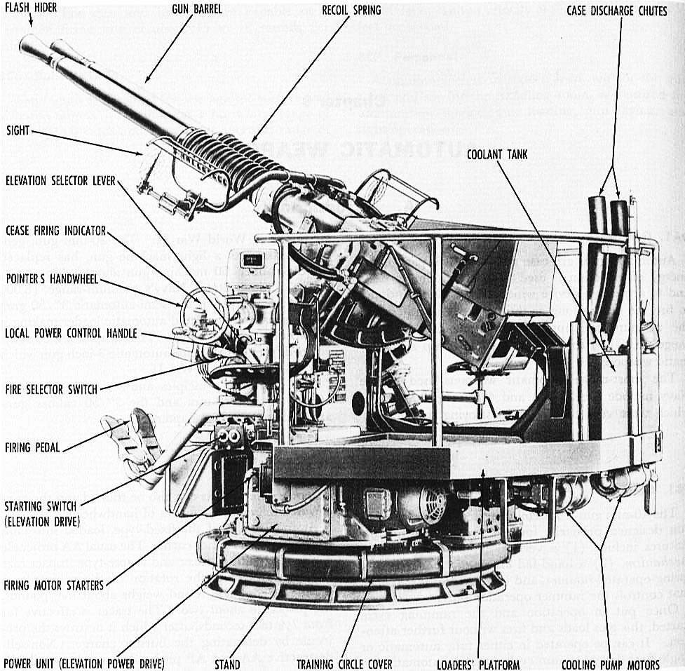
1.1-inch/75-caliber gun (28 mm)
Nicknamed “Chicago Piano”, in reference to the prohibition gangs of the namesake city, this (in)famous artillery piece was the early standard of Anti-Aicraft light gunnery, alongside the heavier 5-in and 3-in dual purpose guns and the puny 0.5 cal. Browning M1920.
Origins and development
This early AA gun gun was based on Richmond-based inventor Robert Hudson’s patents. He create a complicated gas-recoil operating system that was adapted to fire the .30-06 Springfield and .50 BMG. The Navy’s Bureau of Ordnance (BuOrd) knew the 0.5 cal. M2 Browning would be unable to deal with the new generation of aircraft and and wanted Hudson’s design to be up-scaled to fire a much larger, high-velocity 1.1 inches (28 mm) cartridge then in development for such applications. This ended as a water-cooled prototype tested at the Dahlgren Division in 1934.
The 1.1 gun was originally intended to deal with dive bombers as horizontal bombers in addition to the .50 machine gun which was to be the “last line”. The whole process started on October 11, 1928, after a Special Board on Naval Ordnance’s meeting on October 17 about 1″ calibers and greater for AA defence. Looking at various designs abroad, notably the British 0.5 cal. pompom, they decided the best path forward would be a 1.1″ machine gun. On December 13, 1928, engineer Mr. C.F. Jeansen looked for the correct ammunition and by March 1929 Mr. Burk and Chadwick designed the gun mechanism. They went for a 2 pounds cartridge fitted with a .92 pound percussion-fuzed head. The mechanism was ready by 1930, tested in March through May 1931. They showed a cyclic rate of 90 r.p.m. and the many issues found were corrected while the cyclic rate rose to 140. Then it was turned to the Naval Gun Factory for production in 1934 under funds from the National Industrial Recovery Act.
Slow production and later delivery
Development however was difficult and it failed to reach its accuracy and reliability objectives for production and Bureau experimentation would ultimately led to dual-purpose, the 5″/38 DP gun. There was nothing acceptable though for the short range category in between the .50 caliber and 1.1″ although the Bureau developed a quadruple mount to make it for its defects by firepower. The 1.1″ was deemed too heavy as a “last-ditch” free mount and still too light to close the gap with the 5-inch when introduced into service from 1938. It was produced until 1942 despite its faults, and replaced by the couple Bofors/Oerlikon which really succeeded them well. In 1940 the Navy was also plagues by insufficient quantities of these guns leading to a critical situation when hell broke loose at Pearl Harbor: If sufficient 5-in/38, Bofors and Oerlikon existed that day, the picture would have been somewhat different for the IJN.
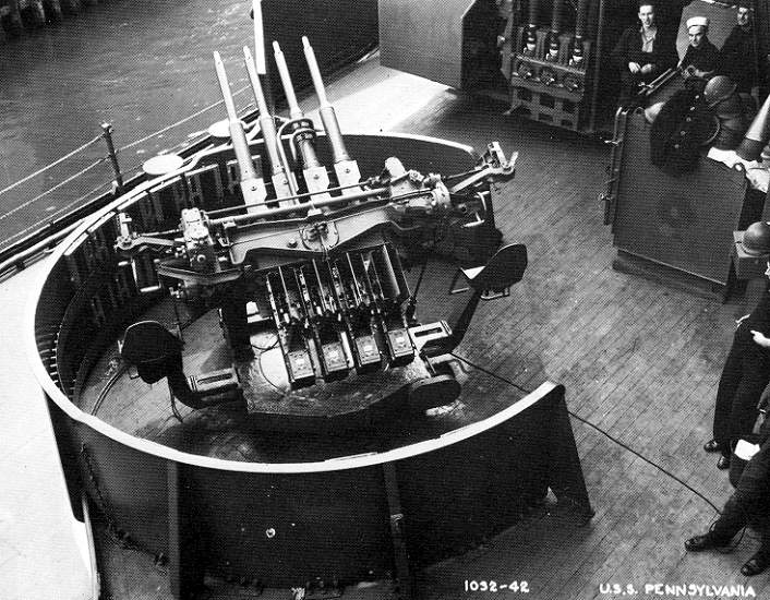
The 1.1 in/75 in WW2
Indeed by 7 December 1941, only five 1.1–inch quad mounts were present at Cavite Navy Yard in the Philippines waiting to be fitted on USS Houston. The spare one left on the dock survived the Japanese bombing and ended on a barge sent to Corregidor. At Pearl Harbor foertunarely most battleships and cruisers present had this mount as primary light AA. Between the time to reach the ammo boxes in times of war and serve the guns, little could be done in the first wave, but they proved their worth in the second, although apparebntly with poor results: There are no records of planes hit by 1.1–inch rounds and it seemed most missed their targets, exploding like hand grenades when back on the ground.
Since they were not replaced before the new 40 and 20mm were available, many ships still sported these as main AA in the firece fighting of 1942. They were gradually replaced in the fleet when having refits and overhauls or repairs, but many sunk with these. The crews did no likes these “chicago piano”. They were too slow and unwieldy, and the fuses never worked properly. They were usually replaced in a one-to-one basis by quad 40mm/60 Bofors whenever available.
Tech specifications |
|
| Mount Lenght | 119.6 in (3.04 m) |
| Total mount weights | 10,500 lb (4,800 kg) |
| Barrel lenght | 82.5 in (2.10 m) bore (75 calibers) |
| Shell | 28 x 199mmSR 0.917 lb (0.416 kg) contact HE. |
| Exact caliber | 28 mm (0.1 inch) |
| Action | API blowback |
| Elevation/Traverse | -15 to 110 degree/360 degrees |
| Rate of fire | 150 rounds per minute |
| Muzzle velocity | 2,700 ft/s (820 m/s) |
| Effective range | 7,000 yd (6,400 m) |
| Recoil | 3.25-inch (83 mm) |
| Feed system | Cylindrical magazine holding 60 rounds |
| Quad mount crew | 15 (1 battery commander, 4 pointers, 4 loaders + 6 assistants) |
20 mm Oerlikon Gun
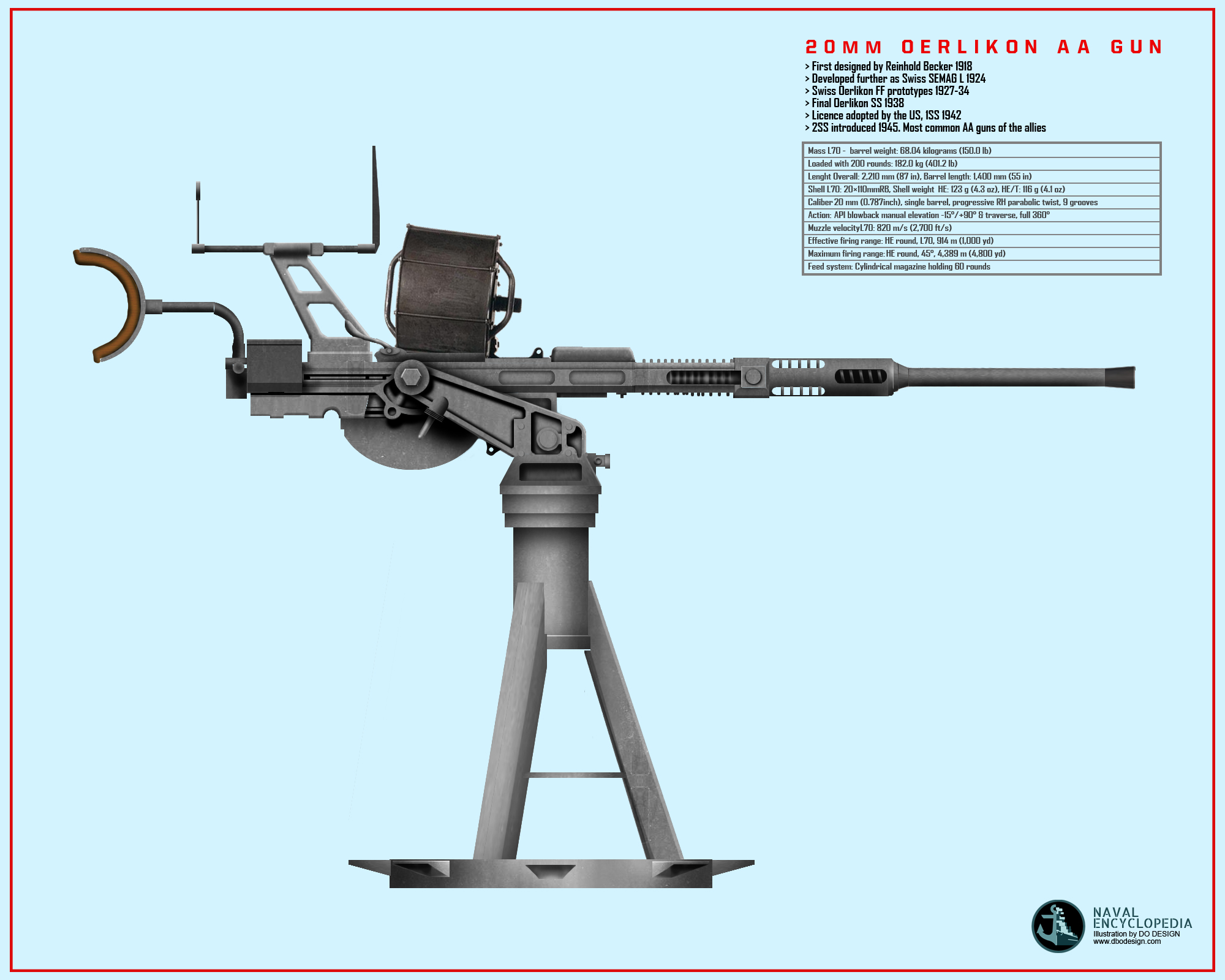
Author’s depiction of the 20mm US-pattern AA gun, shielded, single mount.
Origin of the design: A 1917 German project
During WWI, German industrialist Reinhold Becker worked on a 20 mm quality cannon, known as the “20 mm Becker” designed to use its seemingly superior primer ignition blowback system. This ordnance used a 20×70mm RB cartridge and had a cyclic rate of three hundred shot per minute. It was first deployed on Luftstreitkräfte warplanes in 1918 and also a anti-aircraft gun in the final days. The Treaty of Versailles banned further manufacturing in Germany so the patents and design works were transferred in 1919 to the Swiss company SEMAG (Seebach Maschinenbau Aktien Gesellschaft). SEMAG continued its improvement until 1924 presenting that year the SEMAG L, a heavier weapon or 40 kgs for the barrel and breechblock alone, firing the more powerful 20× 100mm RB ammunition at 350 rpm. However SEMAG failed to produce the model or attract orders and the Oerlikon company purchased the company, received all rights to the weapon, machinery and employees of SEMAG.
The Swiss Oerlikon lineage
In 1927 the Oerlikon S was delivered and reached production stage, firing a larger cartridge (20 x 110mm RB) for a better muzzle velocity of 830 m/s (versus 490 m/s for the Becker), but it was heavier and slower at 280 rpm. Oerlikon then focused on improving its performance for anti-tank and anti-aircraft uses, requiring a much higher muzzle speed. An advanced model called the 1S was designed and produced in 1930. Three types were developped in parralel, divering in ammunition and barrel length but sharing a similar mechanism. Soon were introduced the Oerlikon AF and AL usble on flexible mounts. The 15-round container magazine was soon replaced by drum magazine holding up to 30 rounds.
In 1935 an other step was crossed by introducing an ammo chain designed to be carried into a fighter wings. It was called “Oerlikon FF” (Flügelfest) and declined into three sizes, FF, FFL and FFS. The FF fired a 20 x 72mm RB and weighed 24 kg, allowing a 550-600 m/s muzzle velocity for 520 rpm. The FFL weighter 30 kg but fired at 675 m/s and 500 rpm. The FFS weighed 39 kg but fired at 830 m/s and 470 rpm. Larger drums were also added as options for ground use. For the FF series a drum of 100 round was even proposed, although military customers soon preferred the more manageable 60-spherical drum, still of a manageable weight and size for a gun crew.
In a context of re-armament across Europe, Oerlikon sells augmented rapidly. Some foreign companies even took licenses for the Oerlikon as a fighter cannon. In France, Hispano-Suiza improveed FFS, known as the Hispano-Suiza HS.7 and Hispano-Suiza HS.9, to become its common axial, propeller hub V-12 engine cannon. In Germany, Ikaria created the MG FF, firing 20 x 80 RB ammunition. The Imperial japanese navy ordered the FF and FFL produced locally as the Type 99-1 and type 99-2. Improvements of the FFS as an AA gun ended in 1938 with the Oerlikon SS. Improvements for the rate of fire ended with the 1SS of 1942, 2SS in 1945 reaching 650 rpm. But this was the SS gun which rapidly becamùe famous. The licence was acquired by the rapidly rearming US Army, Navy and Air Force in 1941, and it soon became the most common allied anti-aircraft gun of WW2. In particular it was widely used by Allied navies, using a 400-grain (26-gram) IMR 4831 smokeless powder charge to propel a 2,000-grain projectile at 850 meters second.
Allied production
The Oerlikon FF was already mounted in some fighters of the 1930s like the Polish PZL P.24G. The Ikaria MG FF found its place in some German aircraft, notably in a propeller-hub fashion onboard the famous Messerschmitt Bf 109. The japanese army had their Type 99-1 cannon used one their Mitsubishi A6M “Zeke”. Hispano-Suiza produced its series of V12 moteur-canon 12X/12Y engines using the H.S.7 or H.S.9, mounted on the Morane-Saulnier M.S.406 and a many other types like the Dewoiting 520 and Arsenal VG33. In naval use, initially the Oerlikon was adopted by Royal Navy as anti-aircraft gun. In 1937–1938 Lord Louis Mountbatten trialed it but it turned unsuccessful. The C-in-C of the Home Fleet, Admiral Sir Roger Backhouse became First Sea Lord and in 1939 nevertheless ordered 1,500 weapons in Switzerland. Due to delays and the outcome in France in June 1940, only 109 guns reached the United Kingdom. They had been mounted on various gun carriages, but on land.
only a few weeks earlier the Oerlikon factory permitted manufacture in the united kingdom under licence however. The Royal Navy managed to smuggle out drawings and files and manufacturing began in Ruislip, London in late 1940. The first production cannons were delivered in March-April, 1941. The RAF used it on its ground AA squadrons in North Africa, the middle East, Italy, and North Western Europe, until replaced by the Bofors 40/L60 in 1943.
The next step was evidently a production in the US, at first when tested from 1942 to replace the inadequate M2 Browning and largely deficient 1.1″/75, heavier and with less mechanical reliability. The licence was acquired and the 20 mm became the staple of AA defense at short stages, practical up to 5 km , compmentary to the better Bofors 40 mm. Its oter great advantage was its reduced size and crew, just one man could fire it, another delivering drum magazines to several mounts.
The gun however needed intensive tracking drills to be efficient. It was largely outdated in 1944 and replaced by the Bofors 40 mm of the last generation when possible, and largely outranged by the 3″/50 Mark 22 gun. But at least it succeed to replace the standard AA in 1941, .50 cal Broning and “Chicago Piano”. On planes however it was less successful, plagued with jamming issues with the ammunition feed. The Royal Canadian navy aslo widely used the Oerlikon gun, using its depression on some case for a use as… anti-submarine gun in the Atlantic. It could straddle U-boats up close when larger guns could not depress enough and Flower-class corvettes crews became proficient at it.
The Oerlikon was further developed into the Polsten gun, designed by Polish engineers in exile in UK, starting production in 1944, used among others on the early Centurion tank in the 1950s.
Technical aspects
This high-powered autocannon used a blowback operation as the bolt isn’t always locked to the breech meanwhile firing. Non-locking blowback design is generally used for lighter weapons, as no locking is needed to achieve greater rate of fire, and using low-power cartridges combined with the static inertia of the bolt and slide, a physical tendency to resist speedy acceleration, in order for the projectile to leave the muzzle, vent gas stress within the barrel and secure the entry of another round when the breech opens. Using 20mm cartridges was quite a move as way heavier than anything tested to that point, but WWI Vickers 0.5 calibers.
The Oerlikon makes use of superior Primer Ignition (API) to enhance the bolt resistance. In API blowback guns, the firing pin fires the cartridge at the same time as the bolt remains journeying forward, in order to mitigate fuel stress. The latter had to overcome the forward momentum of the bolt pushing rearwards and to facilitate this, the Oerlikon’s chamber is longer than usual, incorporating the cartridge, front-stop of the bolt of the same diameter.
This extended chamber in the back of the cartridge had the ahead force of the bolt springs against the force of the propellant gases, until the latter triumph and starts pushing the case and bolt springing backwards. If the bolt had stopped at the mouth of the chamber lieke in usual blowback guns, this momentum could had been neutralized; Thanks to the continuous movement a very precise timely setup had the propellant gas force and gradual rearward tour of the cartridge and bolt all ynch perfectly.
There was a second benefit of this unusual arrangement, in which when firing the bolt and case there was a massive distance to travel rearwards before the bolt re-emerges and the case in turn start to go away from the chamber. This aggregate with the deceleration and provides enough time for gas strain to drop back to essential secure stage. This device lets the blowback effect to be used in a way only possible on extra powerful weapons. Compared to weapons with a locking mechanism and heavy bolt, a large spring is required but the Oerlikons had distinctively this component wrapped round the barrel instead as internal. This unique features limit the rate of fire but different steps were taken to improve this, notably within the final version of the Japanese Type 99-2.
This unique chamber and bolt layout needed a commonly shaped cartridg with a case with facets, very little neck and rebated rim. Straight facets allowed to slide back and forward smoothly and precisely inside the cylindrical chamber. The neck when no longer supported expands while the case is fired, and the rebated rim allowed the face of the bolt with its extractor claw hooked over it to fit perfectly inside the chamber. To ease this motion the ammunition needed to be greased however, a major drawback whe operating intensively the Oerlikon cannon.
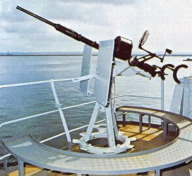
Later during WW2 was developed the “fluted chamber” which had grooves allowing propellant gasses to seep between the chamber wall and case, partly replacing grease by virtues of ultra-fast fluid mechanics. Ammunition feed typically is made using a 60-spherical drum magazine affixed at the top of the gun. In sustained firing, the magazine was frequently changed but at the oher hand Belt-fed versions failed to reach a satisfactory reliability. The gunner to fire had his trigger in the right-hand grip. The entire barrel rested on his shoulders via two extensions with rubber-padded arched bars and waist-belt.
The regular naval model was attached to a loose-swinging, on a fixed pedestal mount, with a flat armored shield affording some basic protection. Dependiong on the mount installation, some had a circular wall offering added procection, with extra magazines alongside. The 20 mm Oerlikon gun was aimed and fired through the usage of a ring-and-bead sight. Some mountings were refined enough to have an height-adjustment feature, adapting to different sized gunners. In extended crews, there was an additional gunnery chief with binoculars designatin targest to the gunner, and an attached reloader, so three men. Dual and quadruple mounts were seomtimes used but rarely on ships as they took as much space as a way superior Bofors.
The USN used quad mounts tailored to fit in their Elco PT boats, the “Thunderbolt” Mount. Prototypes were built and tested iin late 1942, operationally deployed in the Mediterranean. It was also used experimentally on the battleships USS Arkansas, Colorado, Maryland, West Virginia, Washington, Massachusetts, and Wyoming.
Tech specifications L70 |
|
| Barrel Lenght | 1,400 mm/2,210 mm (87 in) oa |
| Barrel/BB weights | 68.04 kilograms (150.0 lb)/20.865 kg (46.00 lb) |
| Fully loaded with 200 rounds | 182.0 kg (401.2 lb) |
| Shell | 20 × 110 mm RB. HE 123 g (4.3 oz), HE/T: 116 g (4.1 oz) |
| Exact caliber | 20 mm (0.787inch) |
| Barrel type | A tube with progressive RH parabolic twist, 9 grooves |
| Action | API blowback |
| Elecation/Traverse | -15°/+90° – 360°, manual |
| Rate of fire | Max 450, Practical 250-320, cyclic 900 rpm |
| Muzzle velocity | 820 m/s (2,700 ft/s) |
| Effective range | 914 m (1,000 yd) |
| Maximum firing range 45° | 4,389 m (4,800 yd) |
| Feed system | Cylindrical magazine holding 60 rounds |
40 mm/L70 Bofors Gun
Who would have thought that most durable and common AA guns of all times would be developed in Sweden (and that in general, the primary allied AA artillery came from traditional neutral countries, Sweden and Switzerland ?). Indeed, the Bofors, from the name of old company that created it, was (and is still) used around the worls, by countles countries, influencing a whole generation of rapid-fire semi-heavy gun. The original was developed by the Swedish arms manufacturer AB Bofors (founded 1646). The venerable manufacturer provided the army and navy of Sweden for centuries. And better still, this universal gun was a produced destined for the Navy.
The company also produced a variety of AA and antitank guns, the Bofors 20 mm Automatic Anti-Aircraft Gun L/70 (1940), the Bofors 25 mm Automatic Gun L/64 (1932), the Bofors 37 mm Anti-Tank Gun L/45 (1935) and Bofors 40 mm Automatic Gun L/43 (a derivative of the L/60 for submarines).
Initial Development: A navy initiative, between Vickers and Nordenfelt
This gun went far in the past considered its duration: In 1922, the Swedish Navy purchased Vicker’s 40 mm 2-pounder “pom-pom” and the navy asked Bofors to develop a better replacement, which after many tests and prototypes, had the company confident enough to signed a contract in 1928. They decided to start from their own 57 mm (6-pounder) semi-automatic gun used by Finspång, essentially a re-barrelled Nordenfelt (another Swedish Company) with a semi-automatic loading mechanism. So the very roots went back to the 1870s…
Tests of a 40mm version of it in 1929 showed the main issue was to feed the gun to reach a good rate of fire. Engineers developed a mechanism strong enough to handle stresses inducced by the large rounds for rapid fire. First attempt was to give the shells zinc shell cases, burning in the chamber when fired. But zinc deposits were a hazard. After many more tests, by the summer of 1930, a brand new test gun was built without controlled feed, tossing spent casing at the rear while a second mechanism using gravity accepted new rounds into the open breech from the clipsed magazine. Firing rate was now acceptable level and an improved prototype was worked on, while Krupp in between took aggressively a 1/3 share of Bofors, feeling this ordnance could well also serve the future German army. Krupp engineers came to update the Bofors factories whereas keeping the 40 mm project in total secrecy.
At last, the 40mm prototype was completed, firing in November 1931, single and soon two and three rounds. The feed mechanism was modified and all the rest was recast and redesigned, until it was able to fire 130 rounds per minute. Then the next concern was to simplify the design and create more durable parts and assembly for mass production. This step was achieved by October 1933. This early model was accepted before and gained the ordnance name of “40 mm akan M/32”. It later became the “Bofors 40 mm L/60” (in reality 56.25 caliber).
-Shells: The basic shell HE weighted 900 g (2.0 lb) and exited the barrel at 2,960 ft/s (900 m/s).
-Cartridge: It used a simple 40 × 311 rimmed brass cartridge.
-Rate of fire on average was 120 rounds per minute, just two every second, helped when the gun was depressed simply because of gravity. Practical it was down to 80–100 rpm due to the initial four round clips replaced by hand.
-Ceiling as tested was 7,200 m (23,600 ft), but due to accuracy concerns, ideal range was 3,800 m (12,500 ft).
-Sights: Intended for a verity of roles, the Bofors 40mm received an advanced sighting system for the time: Trainer and layer had reflector sights for aiming and the commander standing behind them standing “adjusted” the whole using a simple mechanical computer. A 6V battery powered it all.
-The British Stiffkey Sight was operated by the gun layer (right) through simple adjusted trapeze seen above the sights.
Last minute change: The Navy is out
At the last minute, in 1934, as the Swedish Navy was about to order it in large quantities, officials changed their mind. For various reasons, the navy staff wanted instead a hand-traversed 13 mm or a 25 mm guns and started to contact… foreign suppliers. Bofors jumped at the occasion and offered a 25 mm version of its 40 mm in 1932, with bigger clips and scaled-down parts, and fortunately Svenska Marinen’s officials selected it. It became the 25 mm M/32, and indeed was soon seen on many ships, but never had the same success as it appeared later.
The earliest production 40 mm instead was thought of by the Swedish Navy as a light dual purpose main gun on submarines. Having a single caliber aboard for AA and antiship purposed was seen as advantageous. For this, Bofors reduced the barrel caliber to 43, but of course this diminished the muzzle velocity to just 700 m/s (2,300 ft/s). A watertight cylinder was designed for the gun to be foldable and retracted inside rapidly. However this proved tricky and after its adoption by the Sjölejonet class, the experience proved disappointing.
The L/60 was ordered instead by the… Dutch Navy, ordering five twin-gun mounts for their new cruiser De Ruyter, in August 1934. For stabilization they used the famous Hazemeyer mount, a Dutch company. This allowed all mounts to be synchronized on target and was sophisticated for the time, with the five mounts operated by one fire-control system. The Royal Navy was much impressed by the whole lot and soon gained interest for tests, alongside the Vickers QF 2-Pdr.
Bofors later developed a towable carriage, feeling welcome army applications, showcased in Belgium in April 1935. It had a set-up process completed in under a minute and soon seduced several armies, with orders coming, with Belgium in August 1935, Poland, Norway, Finland, and many others… and the Swedish Army as “40 mm lvakan m/36” in 1936.
At last, the Swedish navy revised its initial jugdment, notably because of the Army adoption, and acquired the revised m/36, as a single-mount, still hand-worked and air-cooled, power-operated and another twin mount, this time water-cooled. The twin air-cooled variant was eventually adopted, and also sold to Argentina, while another was developed for Polish submarines. By that time, three navies had adopted it.
British Interest and mass production
The British Army first examined the 40mm L60 in 1937, all Polish-built, for testing. Designated “QF 40 mm Mark I” only the barrel flash hider was modified, leading to the “Mark I/2”. A licence was acquired from Bofors eventually. It was converted from metric to imperial measures and other changes were for mass production. In Bofors indeed, it was still milled, cast and hand-assembled. The process took time and hand assembly still took a great deal. It was soon adopted by the RAAF for field defence, and the Army. It was found that aiming it at an high-speed aircraft degraded accuracy, and for it, developed the most complex system ever devised, the Kerrison Director, an analogue computer driving laying electrically. It proved faster than the human eye and soon became a staple of British production. This also scaled down the crew to three.
By the start of WW2, the BEF arrived in France with as organic AA defence the QF 40 mm Mark III. It proved by far the best allied AA gun in the field. However only 233 had been delivered so far. It was also found the Kerrison Director was sensible and complex to setup. It was produced in few numbers and meanwhile, a gunnery school came with a much simpler device, which however needed a fourth crew member: It was a trapeze-like arrangement, moving the pancake (spiderweb) sight, offering lead correction.
The very advanced, 6 barrel Mark VI adopted in 1945 and seen postwar on many British ships (reddit).
The British Naval Bofors
Soon, the Navy adopted the initial air-cooled versions which saw their baptism of fire by May 1940, during the withdrawal from Norway. With the invasion, a Dutch minelayer, HNLMS Willem van der Zaan, took refuge in UK and brought with her a water-cooled version, on the Hazemeyer tri-axially stabilized mount. It was tested and found brillant. Production started slowly in 1942, with the “QF 40 mm Mark IV” which existed only in twin-mount, while the “QF 40 mm Mark V” was the single mounts. Soon appeared also the Mark VII, up to Mark XI. The USN gained interest in 1942, when procured the Mark V and Mark IV on its simplified “utility” mounting. It was based on the USN Mark I mounting and capable of remote fire control.
The Mark VI was an experimental six-barreled fed by large trays, remote control with a dedicated radar-equipped director. It was long to develop and only shown on HMS Vanguard.
The Mark VII had a hydraulically-powered mounting and replaced the Mark III in 1945.
The Mark IX was an eletrically-powered version of the latter, which became the staple of Coldwar Bofors use, seeing service until the 1990s, notably in the Falklands War. It was equipped of the Stabilized Tachymetric system developed in the 1950s.
The USN Bofors
The USN Bureau of Ordnance purchased a twin-mount and air-cooled models with its spare parts and 3,000 rounds, but from Bofors, arriving in New York by 28 August 1940 aboard USAT American Legion also evacuating the Norwegian royal family through Petsamo. Van Kinsbergen demonstrated while in Britain its Hazemeyer mount to USN in Britain, and itw as quickly chosen as the new standard to replace the quad 28 mm “Chicago Piano”. It was compared to the British 40 mm 2-pdr pom-pom through and found far more promising. Licence negotiations with Bofors stalled until agreement was taken on US airplane export and manufacturing licenses. They ignored at the time the Navy already secretly imported some from Britain, and already started an illegal production as negociations dragged on. The formal contract with Bofors was signed in June 1941 and the Mark 1/2 (for the left and right side of a twin mount) were adapted by Chrysler, as water cooled.
Of course after 7 December 1941, the 1.1″/50 quad mount was declared inadequate and replacemtn agreed by both the new 40 mm Bofors and 20 mm Oerlikon. The water-cooled Bofors was proper to the USN and Coast Guard. The trademark quadruple mount was developed the short way, by taking two twin mounts and fit them side by side, hence the important gap between the two pairs. They were fitted in a standardized walled platform with strapping rails for spare magazines all around. Electricl power operation was another improvement. The quad mount became the staple of AA defence and by 1945 the mass of statistics and reports clearly made the 20mm redundant. It was gradually discarded and replaced by more 40mm and the newly developed twin 3″/50 Mark 27, large enough to fire the new “VT” proximity fuse shell. Unlike the Bofors it was also developed as an anti-ship missile gun. But the 40mm soldiered on in the Korean War and the Reserve fleet ships until the late 1970s. Many surplus were sold and found around the world. It became the facto one of the most common cold war light gun.
Production by the US was undertook by Chrysler, which built 60,000 guns, 120,000 barrels at half the original projected cost, both for the Navy and Army, until 1943 for the latter. Numerous production changes improved mass production, until reducing the time by 50%. Soon York Safe & Lock also started producing it, as well as Naval Gun Factory in July 1943. It was a complex endeavour still, with some 2,000 subcontractors in 330 cities, 12 Chrysler factories and original metric Swedish drawings to be converted. Chrysler made it all, its engineers workong on simplifications and looking for improvements but they only culminated into a new model after 1945.
Tech specifications Bofors L60 |
|
| Barrel Lenght | 1,400 mm/2,210 mm (87 in) oa |
| Barrel/BB weights | 68.04 kilograms (150.0 lb)/20.865 kg (46.00 lb) |
| Fully loaded with 200 rounds | 182.0 kg (401.2 lb) |
| Shell | 20 × 110 mm RB. HE 123 g (4.3 oz), HE/T: 116 g (4.1 oz) |
| Exact caliber | 20 mm (0.787inch) |
| Barrel type | A tube with progressive RH parabolic twist, 9 grooves |
| Action | API blowback |
| Elecation/Traverse | -15°/+90° – 360°, manual |
| Rate of fire | Max 450, Practical 250-320, cyclic 900 rpm |
| Muzzle velocity | 820 m/s (2,700 ft/s) |
| Effective range | 914 m (1,000 yd) |
| Maximum firing range 45° | 4,389 m (4,800 yd) |
| Feed system | Cylindrical magazine holding 60 rounds |
5-in/25 DP gun
The 5″/25 caliber gun entered service as standard heavy anti-aircraft ordnance, entering service just in time for the new Washington Naval Treaty cruisers commissioned in the interwar. The engineers at the time tried to create a gun powerful yet light enough to be rapidly trained manually. It ended as well mounted on pre-WWII battleships and aircraft carriers until replaced by famous dual-purpose 5″/38 caliber gun derived it. 5-in/25 removed from battleshipsended on new submarines also by late 1943, until replacement by a new one by mid-1944,. The name was for 5 inches (127 mm) in diameter, 25 calibers long for the barrel or 125 inches, 3.2 meters. It was sometimes used as a dual-purpose gun but was kept mostly as anti-aircraft gun.
Firing on USS Saratoga
⚙ specifications 5-in/25 |
|
| Weight | |
| Barrel lenght | 11 ft 10 in (3.6 m)oa, barrel 10 ft 5 in (3,175 mm) |
| Elevation/Traverse | -10° to +85°, mounting dependent |
| Loading system | |
| Muzzle velocity | 2,100 ft/s (640 m/s) average |
| Range | 14,500 yards (13,300 m) at 40°/27,400 feet (8,400 m) at 85° |
| Guidance | Visual tracking + telemetry |
| Crew | 8 |
| Round | 127 × 626 mm R fixed or semi-fixed 52 to 54.5 lb (23.6 to 24.7 kg) |
| Rate of Fire | |
5-in/38 DP gun
The third “pillar” of USN AA defence in WW2 was provided by the unbiquitous 5-in/38 gun.
The ten Mark 28 Mod 0 turrets ith their enclosed base ring mounts supporting twin Mark 12 guns were plced as follows: Two on deck level amidships and three on the battery deck alternated, on either side, so ten turrets in all for twenty guns, all independent. Probably the best ordnance piece of equipment on the allied side, and credited as such by admirals in their role especially at the end of WW2 with the level of Kamikaze attacks, these famous weapons systems were taking advantage of the standard 5-inches (127 mm) classic gun caliber used by the USN since even before the dreadnought age. These new ones were initially designed to be mounted on destroyers the new 1930s destroyers. Read More: 123
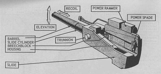
Gun assembly (ONI, cc)
But it soon appeared so successful that a myriad of US ships received them, in fact from destroyers to cruisers, battleships and aircraft carriers until 1945. “highly reliable, robust and accurate” they were the perfect dual purpose guns, as their anti-air abilities established in 1941 gunnery tests on board North Carolina proved an amazing accuracy agains fast flying tarets up to 12,000–13,000 feet (3.7–4.0 km) twice as far as the older 5-inch/25 AA model used so far. Fuses shells soon also added a great bonus, and later in WW2, progresses in radar-assisted guidance made them supremely deadly. It’s not at random they were still active on modernized FRAM destroyers in the 1990s around the world… This installation in a “W” pattern not only was convernient to give them the best arc of fire, but also ensured no inteference with other systems, helped with the broad beam at this point.
Quickspecs:
-Guns Weight
–
-Bore length
-Rifling length
-Muzzle velocity 2,500–2,600 ft/s (760–790 m/s)
-Barrel life 4,600 rounds
-Depression/Elevation −15 and 85° at 15° per second.
−Traverse 150-150° on either side for battery guns (with interruptor gear)
−Traverse 80-80 degrees for deck turrets, both at 25°/sec.
-Rate of fire as designed 15 rpm
-Vertical sliding-wedge with 15 in (38 cm) recoil
Tech specifications 5-in/38 Mk.12 |
|
| Gun Lenght | 223.8 in (5,680 mm) long overall |
| Gun wight | 4,000 lb (1,800 kg) without breech. Mount weight 156,295 pounds (70,894 kg). |
| Bore Lenght | |
| Rifling | 157.2 in (3,990 mm). |
| Shell | 20 × 110 mm RB. HE 123 g (4.3 oz), HE/T: 116 g (4.1 oz) |
| Exact caliber | 127×680mmR 53-55 lb (24-25 kg) shell |
| Action | API blowback |
| Elecation/Traverse | -15°/+90° – 360°, manual |
| Rate of fire | Max 450, Practical 250-320, cyclic 900 rpm |
| Muzzle velocity | 820 m/s (2,700 ft/s) |
| Effective range | 914 m (1,000 yd) |
| Maximum firing range 45° | 4,389 m (4,800 yd) |
| Feed system | Cylindrical magazine holding 60 rounds |
The standard battery seen on the North Carolina and South Dakota class: Twenty 5 in (127 mm)/38 caliber Mark 12 in twin turrets. They were placed along the superstructure, in two rows and superfiring, alternated position to reach the best possible arc of fire at about 180° either side. This did not changed during WW2, albeit AA artillery did.
These turrets were of the Mark 28 Mod 2 twin dual-purpose mount type, weighting 56,295 lb (70,894 kg) and capable of −15 degrees to 85 degrees. They fired AA, illumination, white phosphorus shells for night fighting at 15–22 rounds per minute. The shell was quickly manually loaded, each weighting 54 and 55 lb (24–25 kg). They could be associated with full charge, a full flashless charge, and reduced charge. Depending on these, muzzle velocity of ranged from 2,500 to 2,600 ft/s (790 m/s). Each turret was supplied by 450 rounds and life expectancy of the barrels was 4,600 rounds.
They were all ten directed by four Mark 37 fire control systems through remote power control (RPC).
 IJN AA Weaponry
13.2 mm Type 93 heavy machine gun

The Type 93 13 mm heavy machine gun (九三式十三粍機銃), Type Ho 13 mm AA machine cannon was a license-built version of the French Hotchkiss M1930 machine gun. It was widely used for heavy ground support and organic for AA defence, until gradually replaced when possible by the 25 mm Type 96. They were still in use, on twin mounts, on many IJN cruisers and destroyers before WW2 but gradually replaced when possible, notably by single 25 mm mounts due to unsufficient range and firepower:
Tech specifications Type 93 heavy machine gun |
|
| Barrel Lenght | 140 centimeters (55 in) total, 988 millimeters (38.9 in) barrel alone |
| Mass | 42 kilograms (93 lb) (empty) |
| Fully loaded | ? |
| Shell | 13.2×99mm Hotchkiss |
| Exact caliber | 13.2 mm |
| Barrel type | A tube with progressive RH parabolic twist, 9 grooves |
| Action | Gas-operated fully automatic |
| Elecation/Traverse | -15 / +85°, 360° traverse, manual |
| Rate of fire | 450 rounds/min Max |
| Muzzle velocity | ? |
| Effective range | 1,000 meters (3,300 ft) |
| Maximum firing range 45° | ? |
| Feed system | Classic box magazine holding 30 rounds |
| Sight | Spiderweb anti-aircraft iron sight |
25 mm Type 96

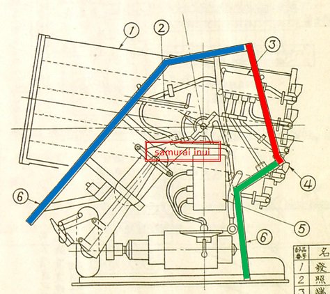
The common twin mount in 1941
The famous type 96 25 mm AT/AA gun became the ubiquitous, do-it-all light gun of the IJA and IJN. This automatic cannon was a locally-developed variant of the French Hotchkiss 25 mm anti-aircraft gun, designed as a dual-purpose against both light armored vehicles and aircraft, but is more generally known as an anti-aircraft gun in single, twin, triple fixed mounts.
It’s original concept lays in 1935 with the will of the Imperial Japanese Navy to replace the WWI era 40 mm Vickers “pom-pom” gun as main AA gun on its ships. After looking in Europe and the US, they settled on the French 25 mm Hotchkiss design (which is a French-American brand in essence). Japanese officers and engineers traveled to France to evaluate it in 1935 as it was just introduced as the organic army AA gun. An order was placed for both guns and several mounts types for evaluation. Firing tests were conducted at Yokosuka Naval Arsenal the same year, and the first tailored for IJN needs built in France under the designation Type 94 and Type 95. Whe tooling was completed in japan, mass production commenced at Yokosuka Arsenal, given the designation Type 96.
Minor changes were made to the original Hotchkiss design as well as for production with new components made from castings and no longer forgings to speed up and simplify production. The simple conical flash suppressor was also replaced by a more elaborated Rheinmetall design. Many mounts were designed, inclusing a wheeled AT gun for the Army, and for the Navy, there was a submarine-mountable version massively using stainless steel to avoid rust.
The Type 96 was an air-cooled gas operated design. The multiple rings around the base of the barrel with a forging screwed into the breech mechanism, was patented by Hotchkiss and in use since 1914. The IJA by the way also brought patents for the 0.3 in (6.5 mm) model and also domestically produced it, as well as declining it into the larger Type 93 heavy machine gun (13.2 mm caliber).
The twin-mount type was the first to enter service. The triple mount was introduced in 1941, and the last was the single mount, in 1943. The latter was an attempt to upgrade firepower of many ships in service with an extra weapon taking little space on deck. In all, it existed in ten models. It was in essence the same philosophy as the allied 20 mm Oerlikon gun. However, for several reasons, the 25 mm was certainly not on par with the latter:
– Elevation and traverse were too slow, even with powered mounts
– The sights were ineffective against high speed targets
– Firing the multiple mounts caused excessive vibration, which reduced accuracy and prevented effective target tracking
– Too little ammunition in each magazine resulted in a low overall rate of fire
– Blinding Flashes from the fire (mitigated over time by new muzzles and cartridges mixtures)
There was also the issue of precise gunnery due to the lack of good sights and presence of a gunnery officers which simply pointed the general direction to gunners operating the predals for elevation and traverse. 20 mm Oerlikon were operated by one man with its spideweb sight, and no time was left between spotting and pointing. This was achieved in 1944 on the single mounts, although there was the need of a loader for each one. 40 mm Bofors in contrast used a fired control radar by 1944 which helped considerably achieve instantly the right bearing. But overall, the general picture for US airmen was that the Type 96 was not accurate, and the Japanese also underestimated the strenght and resilience of US planes. It happened they survived direct or indirect impacts too often for comfort. Tracers could have helped, but space in these small ammo boxes was such that a little could be spared and there were generally only one or two per 15 rounds.
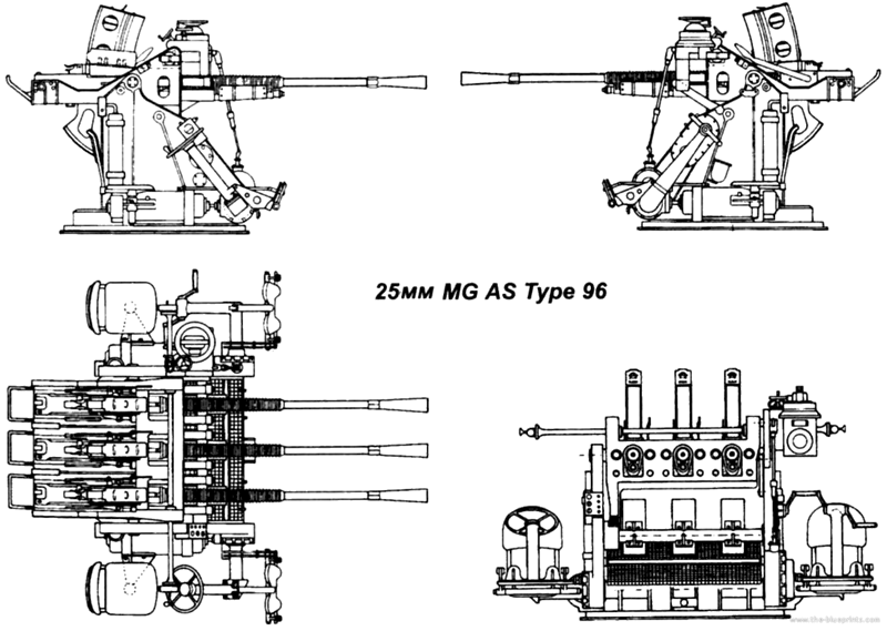
A technical rendition of the triple mount, most common on IJN warships
Tech specifications 25 mm Type 96 |
|
| Barrel Lenght | 1.5 m (4 ft 11 in) L/60 |
| Barrel weights: Single | 785 kg (1,731 lb) |
| Barrel weights: Twin | 1,100 kg (2,400 lb) |
| Barrel weights: Triple | 1,800 kg (4,000 lb) |
| Crew: | 3, 7 and 9 respectively |
| Shell | 25×163mm |
| Exact caliber | 25 mm (0.98 in) |
| Action | Gas operated |
| Elecation/Traverse | -10°/+85° – 360°, manual |
| Rate of fire | 200–260 rpm (cyclic) |
| Muzzle velocity | 820 m/s (2,700 ft/s) |
| Effective range | 6.8 km (4.2 mi) at 45° with HE shell |
| Maximum firing range 85° | 3 km (9,800 ft) effective, 5.5 km (18,000 ft) max. |
| Feed system | 15-round box magazine |
| Production | 33,000 all variants 1935-45 |
5-in (127mm)/40 Type 89
The standard dual purpose artillery of the IJN. The 12.7 cm/40 Type 89 naval gun (40 Kokei Hachikyu Shiki 12 Senchi 7 Kokakuho) was mostly used as heavy AA gun. It was adopted on February 6, 1932 (hence the Type, based on the Japanese calendar), becoming the primary long range AA gun on aircraft carriers, battleships and cruisers, almost always in twin gun mounts. It was also used by smaller vessels such as the Matsu-class escort destroyers. They replaced the older 8 cm/40 3rd Year Type naval gun and 12 cm/45 10th Year Types. They were supposed to be replaced by the new 100mm/65 (4 in) guns type 98 but only IJN Taiho and some “super destroyers” were so equipped due to shortages.
Specs 5-in IJN DP Type 89 |
|
| Barrel Lenght | 5,080 millimeters (16 ft 8 in) (bore length) |
| Mass | 3,100 kilograms (6,834 lb) |
| Shell | Fixed 127 x 580mm .R 20.9–23.45 kilograms (46.1–51.7 lb) |
| Exact caliber | 12.7-centimeter (5.0 in) |
| Elevation/Traverse | -8° to +90°, manual |
| Rate of fire | 8-14 rounds per minute |
| Muzzle velocity | 720–725 meters per second (2,360–2,380 ft/s) |
| Effective range | 14,800 meters (48,600 ft) at 45° |
| Ceiling at 90° | 9,440 meters (30,970 ft) |
| Feed system | Manual horizontal breech block |
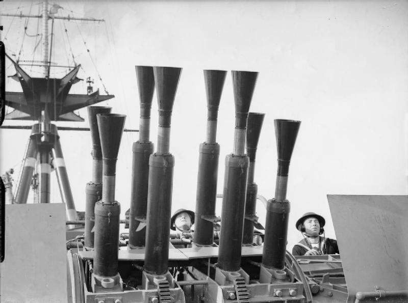
5-in (127mm) 28-barrel Type 02 AARL
These AA spin-stabilized rockets inspired by German and domestic works, was a quick and intense firepower solution developed in 1944. The idea was to cover the largest blast area in the shortest time possible, overwhelming an air attack. On paper it was very efficient since each mount could delivered in rapid succession twenty-eight 5-in rockets, with incendiary shrapnel warheads. The latter were close to the “Sankaidan” Type 3 gun shells. The time fuze had two settings, 1,000 or 1,500 meters (1,100 or 1,640 yards). Maximum Range was 5,250 yards (4,800 m) and maximium ceiling at 80°, about 7,545 feet (2,300 m). Very few action reports exist on them, so it’s difficult to assess their effectiveness. More on these. ➚ See also the ONI report, p15-16. ➚ or this source (in japanese) ➚.
Cold War Guns
Development or artillery, although questioned seriously as missiles developed in the 1950s, was never abandoned. In fact innovations are still made, and they still are part of everyday’s warships. They are usually on larger vessels seen as the trusted “short range backup”, for defense against aviation or surface vessels alike. With automated reloading and radar-controlled fire control systems, the human factor is barely in the equation anymore. But to reach that level, it took the entire 42 years of the cold war, and the incentive of the rivalry between NATO and the Wardaw Pact to perfect these solutions.
In 1946, the average naval gun, either heavy (cruisers and battleships) was still manual, but with the help of semi-automated systems for reload and handling of ammunitions, which could be very large; AA artillery, of smaller caliber, benefited from developments in autocannons and heavy machine guns, and basically were a far away inheritor of the QF guns at the end of XIXth Century, with perhaps the Gatling gun as an early reference. In fact the same Gatling rotating barrel is still in the inventory today as part of the CIWS close defence system and assimilated. They are mostly use for last resource antimissile system, alongside chaffs and ECM. On Frigates and Destroyers today, the usual calibers are generally ranging from the classic 5-in (120 mm) to the 4-in (100 mm) and 3-in (76 mm) with 40, 37, 30 and 20 mm still in favor. The good old “ma deuce”, the venerable Browning M2HB is also often present on many NATO warships and beyond.
The 1960s saw for the USN a very unique solution to “modernize” existing battleships, even allowing them to take part in the wider US deterrence policy as one Iowa-class vessel was tailored to carry a serie of “Katie”, a nuclear-tipped 16-in shell. It is unclear (not denied specifically by the USN) if these were ever carried. This probably was a force multiplier, before cruiser missiles with that capability like the Harpoon were introduced in the 1980s.
Thanks to DARPA and the USN also still leads the pack in terms of direct action weaponry, between lasers and ultra-velocity guns. The large Zumwalt class (2016) as a backup reintroduced the 155 mm (6 in)/62 caliber with the “Advanced Gun System” but it remained inoperable and the two forward turrets are still not operational. The original plan called for an electric railgun. Some tests proved that the projectile does not need any wahread per sea. Like APFSDS rounds for tanks, the idea is terminal velocity creates enough energy to destroy the target by itself. Tests performed at the Naval Surface Warfare Center Dahlgren Division in the 2000s showed that the given tungsten or uranium projectile could reach 2,500 m/s (8,200 ft/s), approximately Mach 7 at sea level or more. Any plane hit would just disintegrate on impact, while it would certainly cripple a ship the same way as any warhead-tipped missile. However, like the laser, the amount of energy necessary is just ludicrous. Good old autocannons still rules the day, and probably will for many more years in the future.
USN Cold War Artillery
5-in/54 Mk.42
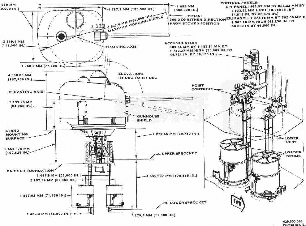
The Mark 42 5″/54 Caliber Gun had the following specs:
- Shell 127 x 835mm .R Conventional 31.75 kg (70.0 lb)
- Recoil 18.75 inches (476.2 mm)
- Elevation -15°/+85° at 25°/sec
- Traverse 150° at 40°/sec
- Rate of fire 40 rpm automatic (28 in 1968)
- Muzzle velocity 2,650 ft/s (807.7 m/s)
- Max range 25,909 yd (23,691.2 m) at +45° elevation
- Ceiling 51,600 ft (15,727.7 m) at +85° elevation
The Mark 42 5″/54 really was a cold war game changer for NATO. Not only it equipped cruisers, destroyers, frigates or the USN, but also was used by Australia, Egypt, Germany, Greece, Japan, Mexico, Spain, Taiwan, Thailand and Turkey, but it stayed in service amazingly well past the 1990s, staying relevant as long as the radar based firing control stayed relevant.
3-in/50 Mk.22
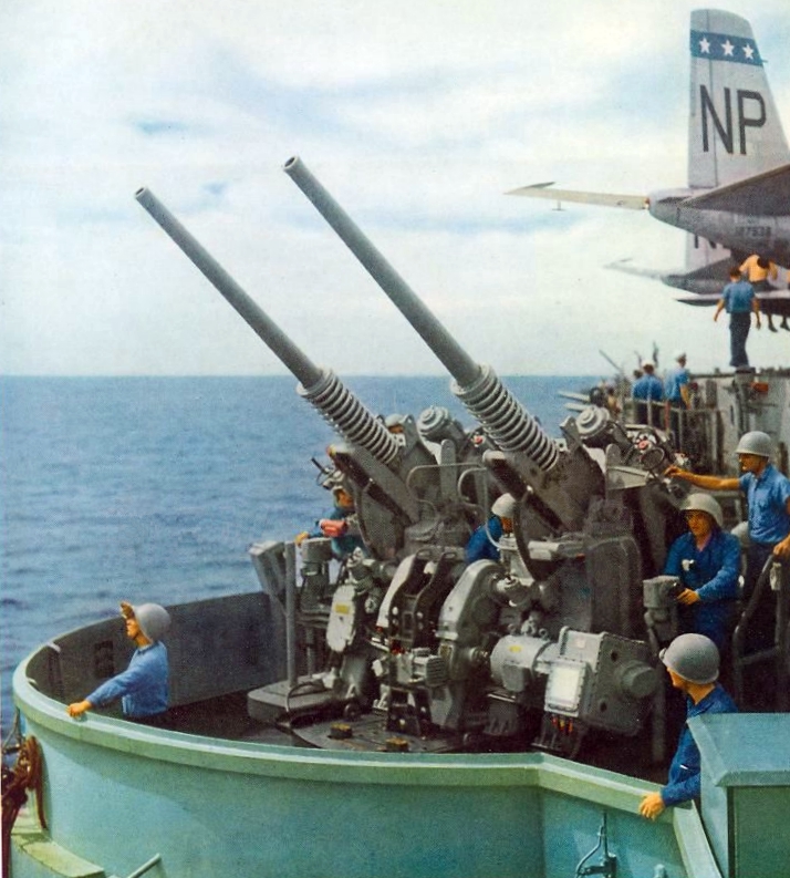
Designed to replace both the Oerlikon 20 mm and Bofors 40 mm guns to counter Japanese kamikaze attack at short ranges the 3″/50 caliber gun was adopted on a Mark 22 mount. It was semiautomatic with a power-driven automatic loader existing either in single and twin mounts. Many WW2 ships had their twin 40 mm simply swapping to a single 3”/50 Mk.27 mount and the quadruple for a twin (Mk.33/34). This was performed in the 1950s on the Essex-class aircraft carriers, Allen M. Sumner and Gearing-class destroyers. Heavier than expected they imposed the deletion of some 40 mm mounts. These were also dual purpose on an open-base-ring type and identital assemblies, common power drive for 30° sec. and elevation from 15 to 85° at 24°/s. Automatic feed came from an on-mount magazine assisted by two loaders.
Normal crew went to eleven men with a mount captain, two control station men, four loaders and four shell “passers” plus a sight setter. For the twin mounts right gun-layer was responsible for the antiship control, the left gun-layer anti-aircraft fire and captain between them. Later, aluminum and fiberglass weather shields could be installed.
The 3-in/50 Mark 22 used a proximity fuze and a fire-control radar for an optimal 50 rpm per barrel. It was found however ineffective against supersonic jets and cruise missiles. FRAM programs thus often imposed the removal of these. The 3″/70 Mark 26 gun were kept a bit longer, until replaced by light SAMs. The second standard of the time, the heavier 5″/54 Mark 42 was considered more effective. The very last of these systems were removed in the early 1990s but some stayed in service under other flags. see also
- Shell 12.13 in (30.8 cm)
- Weight Mark 31 Mod 1: 24 lbs. (10.9 kg)
- Elevation -15°/+85° at 30°/sec
- Traverse 360° at 24°/sec
- Rate of fire 40 rpm automatic (28 in 1968)
- Muzzle velocity 2,700 fps (823 mps)
- Antiship range (45°): 14,600 yards (13,350 m)
- AA ceiling (85°): 30,400 feet (9,266 m)
3-in/70 Mk.22
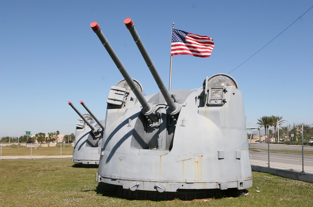
Development started in 1945 to replace the 20 and 40 mm standard AA to stop Kamikaze attacks and both the need for a larger-caliber and better (radar guised) accuracy were part of the specifications. The postwar 3″/50 (7.62 cm) Mark 33 had autoloaders and this led to the final 3″/70 (7.62 cm) programme, based on the fact it was smallest-size projectile fitted with a radar proximity fuze. BuOrd wanted a closer twin mounting compared to the Mark 33 3-in/50 mount.
Eventually it was designed replace the venerable, standard 5″/38 (12.7 cm) on Mark 12 mount, in one for one basis, so any ship could swap them postwar without much redesign. This new mount in fact became the new destroyer standard but it was complex and development took until 1956. The initial mounting was very unreliable and near-impossible to maintain, and the whole system was quickly replaced. It only offered the advantage of a weather gun shield. In the end, USS Norfolk (DL-1) kept these long after the Mitscher. More on navweaps
- Shell weight (complete) 36 lbs. (16.4 kg)1a
- Shell size Mark 10 – 76.2 mm x 669R
- Elevation -15°/+90° at 35°/sec
- Traverse 360° at 50°/sec
- Rate of fire 40 rpm automatic (28 in 1968)
- Muzzle velocity 3,400 fps (1,036 mps)
- Antiship range (45°): 19,500 yards (17,830 m)
- AA ceiling (90°): 38,000 feet (11,580 m)
Antimissile artillery
The development of anti-missile rapid fire guns, CIWS, Phalanx, but also Chaffs, ECM and other countermeasures.
20 mm Phalanx CIWS (1978)
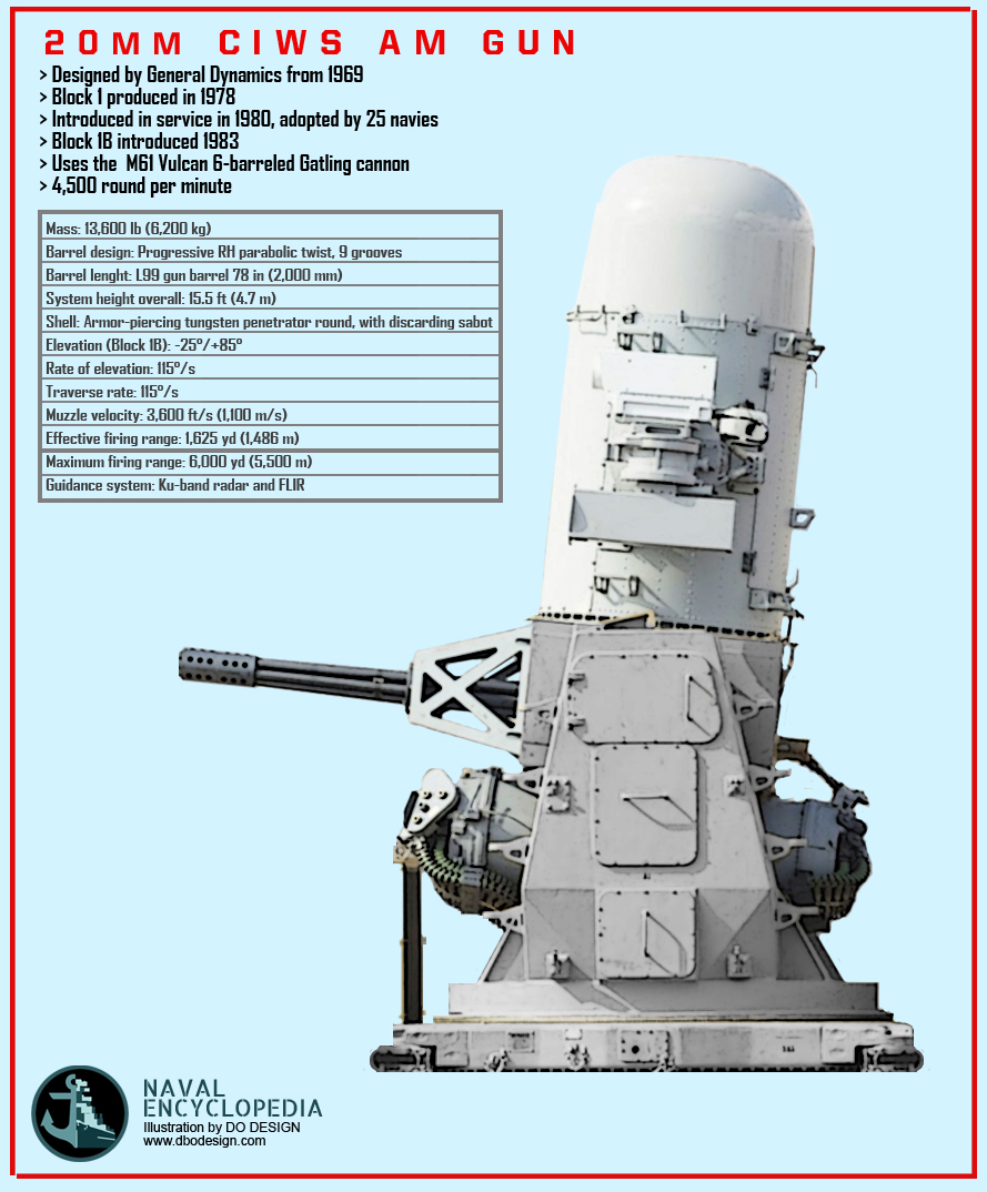
The 20mm Vulcan-Phalanx system, adopted by the USN in 1978 is still today the main automated hyper-fast autocannon using a rotative barrel (Gatling system) to reach an exceptionally high rate of fire. It is designed to destroy an incoming missile’s airframe. Loosing its aerodynamic qualities while shrapnel secondary damage is a bonus, to destroy potentially electronics systems. The key of the system is that it’s unmanned, but with human oversight. The tracking system is faster than the human brain can process the target acquisition. Another advantage of the system is that it can also destroy low-fliying aircrafts if needed or even deal with small and fast surface targets. Developed from 1969 and produced from 1978, it was constantly upgraded until today. The last system used on the Forrestal class were Mk.15 Block 1B which unit cost was US$416M. The data is for the Block 1B.
- Mass: 13,600 lb (6,200 kg)
- Barrel design: Progressive RH parabolic twist, 9 grooves
- Barrel lenght: L99 gun barrel 78 in (2,000 mm)
- System height overall: 15.5 ft (4.7 m)
- Shell: Armor-piercing tungsten penetrator round, with discarding sabot
- Elevation (Block 1B): -25°/+85°
- Rate of elevation: 115°/s
- Traverse rate: 115°/s
- Muzzle velocity: 3,600 ft/s (1,100 m/s)
- Effective firing range: 1,625 yd (1,486 m)
- Maximum firing range: 6,000 yd (5,500 m)
- Guidance system: Ku-band radar and FLIR
 Latest Facebook Entry -
  X(Tweeter) Naval Encyclopedia's deck archive
 Instagram (@navalencyc)


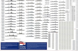
 French Navy
 Royal Navy
 Russian Navy
 Armada Espanola
 Austrian Navy
 K.u.K. Kriegsmarine
 Dansk Marine
 Nautiko Hellenon
 Koninklije Marine 1870
 Marinha do Brasil
 Osmanlı Donanması
 Marina Do Peru
 Marinha do Portugal
 Regia Marina 1870
 Nihhon Kaigun 1870
 Preußische Marine 1870
 Russkiy Flot 1870
 Svenska marinen
 Søværnet
 Union Navy
 Confederate Navy
 Armada de Argentina
 Imperial Chinese Navy
 Marinha do Portugal
 Mexico
 Kaiserliche Marine
 1898 US Navy
 Sovietskiy Flot
 Royal Canadian Navy
 Royal Australian Navy
 RNZN Fleet
 Chinese Navy 1937
 Kriegsmarine
 Chilean Navy
 Danish Navy
 Finnish Navy
 Hellenic Navy
 Polish Navy
 Romanian Navy
 Turkish Navy
 Royal Yugoslav Navy
 Royal Thai Navy
 Minor Navies
 Albania
 Austria
 Belgium
 Columbia
 Costa Rica
 Cuba
Cuba Czechoslovakia
 Dominican Republic
 Haiti
Haiti Hungary
 Honduras
 Estonia
 Iceland
 Eire
Eire Equador
 Iran
Iran Iraq
Iraq Latvia
 Liberia
 Lithuania
 Mandchukuo
 Morocco
 Nicaragua
 Persia
 San Salvador
 Sarawak
 Uruguay
 Venezuela
 Zanzibar
 Warsaw Pact Navies
 Bulgaria
 Hungary

 Bundesmarine
 Dutch Navy
 Hellenic Navy
 Marina Militare
 Yugoslav Navy
 Chinese Navy
 Indian Navy
 Indonesian Navy
 JMSDF
JMSDF North Korean Navy
 Pakistani Navy
 Philippines Navy
 ROKN
ROKN Rep. of Singapore Navy
 Taiwanese Navy
 IDF Navy
 Saudi Navy
 Royal New Zealand Navy
 Egyptian Navy
 South African Navy


 Ukrainian Navy