
Category: ww1 warships
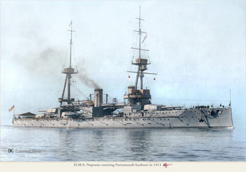
HMS Neptune (1902)
United Kingdom (launched 1909) Dreadnought Battleship (service 1911-1921) HMS Neptune was a figurehead of a new class of dreadnoughts, but…
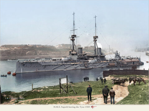
Bellerophon class battleships
Royal Navy (1907) – Bellerophon, Superb, Temeraire By December 1906, after the famous battleship was launched, 1st lord of the…
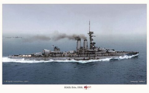
Battleship HMS Erin
HMS Erin (ex-Reshadieh) 1913 HMS Erin was a one-off dreadnought battleship ordered initially by the Ottoman from the Vickers Armstrong…
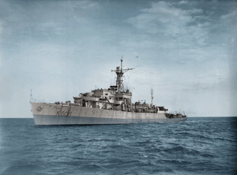
Bay class Frigates (1945)
United Kingdom – (1943-45): 26 Loch converted to Bay class. The Bay class were 26 anti-aircraft frigates built for the…
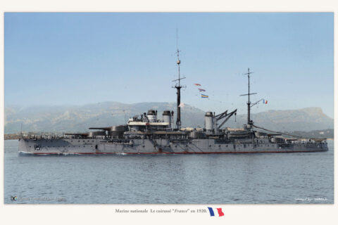
Courbet class Dreadnought Battleships (1911)
France (1911) – Courbet, Paris, France, Jean Bart (ex-Ocean) France’s first dreadnoughts The Four Courbet class were the first French…
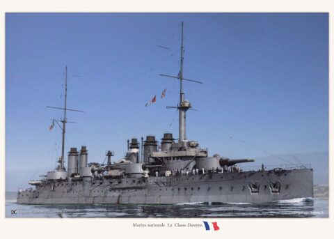
Danton class Battleships (1909)
France (1909) Condorcet, Danton, Diderot, Mirabeau, Vergniaud, Voltaire The six Dantons were the last French pre-dreadnoughts. They had the misfortune…
Diadem class armoured cruisers (1896)
RN (Built 1896-1903): HMS Diadem, Amphitrite, Andromeda, Argonaut, Ariadne, Europa, Niobe, Spartiate The eight Diadem signed an attempt to stand…
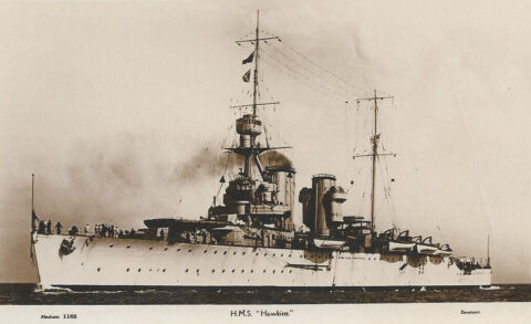
Hawkins class cruisers (1920)
British Royal Navy (1920): Hawkins, Frobisher, Effingham, Raleigh, Cavendish/Vindictive Named the “Elisabethan Corsairs” due to their names, the Hawkins-class cruisers…
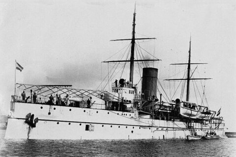
Koningin Regentes class Coast Defence Ships (1900)
Royal Netherlands Navy 18904-1968: HNLMS Koningin Regentes, De Ruyter, Hertog Hendrik The three Koningin Regentes class Coast Defence Ships (pantserschep)…
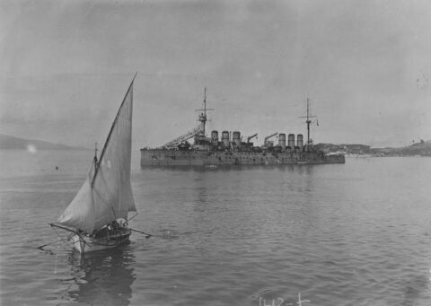
Ernest Renan (1906)
France. Armored Cruiser built 1904-1908, service until 1937. Ernest Renan was the penultimate French armored cruiser, launched the same year…