
Category: ww1 warships
Generali class destroyers (1920)
Regia Marina – 6 destroyers: Generale Antonio Cantore, A. Cascino, A. Chinotto, C. Montaranari, M. Prestinari, A. papa. Built 1919-1922,…
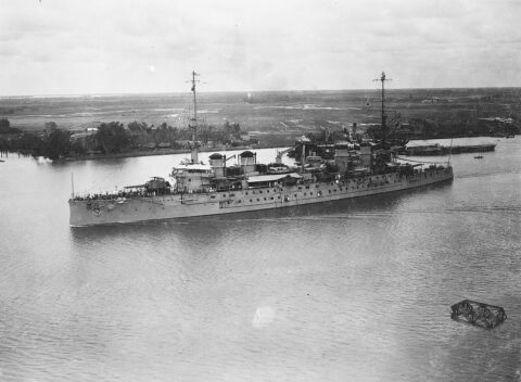
Jules Michelet (1905)
France. Armored Cruiser built 1904-1908, service until 1937. Jules Michelet was an evoliution of the previous Leon Gambetta armoured cruiser…
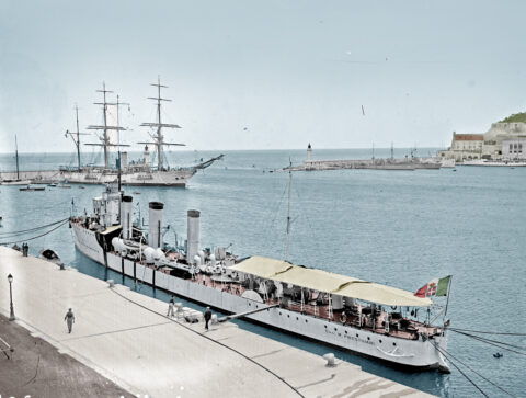
Giuseppe La Masa class destroyers (1918)
Regia Marina – 8 destroyers: Giuseppe La Masa, Giacinto Carini, Benedetto Cairoli, Angelo Bassini, Nicola Fabrizi, Giuseppe La Farina, Agostino…
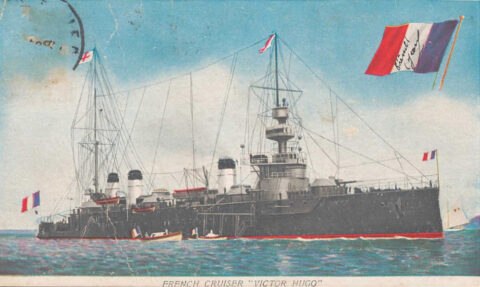
Léon Gambetta class Armoured Cruiser (1902)
France. Built 1901-1907, service until 1928: Armored Cruiser Léon Gambetta (1903), Jules Ferry (1903), Victor Hugo (1904). The Léon Gambetta…
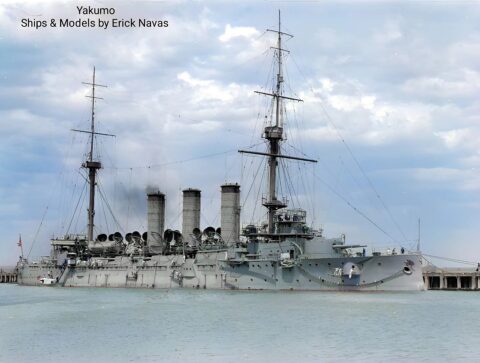
IJN Yakumo (1899)
Nihhon Kaigun (1900-1922): Armoured Cruiser (Sōkō jun’yōkan) Yakumo (“Eight Clouds”) was an armored cruiser built for the Imperial Japanese Navy…
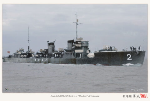
Minekaze class destroyers (1918)
Destroyers built 1919-23, Minekaze, Okikaze, Shimakaze, Nadakaze, Tachikaze, Hokaze, Nokaze, Namikaze, Numakaze, Sawakaze, Yakaze, Hakaze, Shiokaze, Akikaze, Yukaze. The Minekaze…
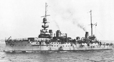
République class Battleships (1904)
French Navy Pre-Dreadnought Battleship: FS République, Patrie (1901-1905) The many shortcomings of the previous classes, born under the Jeune Ecole…
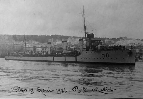
Giuseppe Sirtori class destroyers (1917)
Regia Marina – 4 destroyers: Giuseppe Sirtori, Giovanni Acerbi, Vincenzo Giordano Orsini, Francesco Stocco 1917-1944 The Giuseppe Sirtori class destroyers…
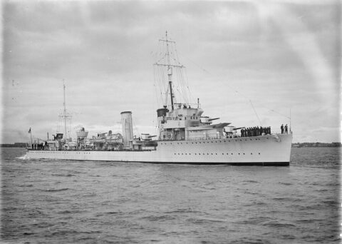
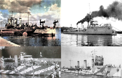
Admiralty type (Scott class) flotilla leaders (1917)
UK Royal Navy (1916-1945) 1916 program: HMS Scott, Bruce, Douglas, Campbell, MackKay, Malcolm, Montrose, Stuart (Built 1916-1920). Second part on…
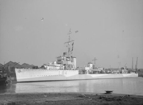
Thornycroft Type (Shakespeare class) Destroyer Leaders (1917)
UK Royal Navy (1916-1945) 1916 program: HMS Shakespeare, Spenser, Wallace, Keppel, Rooke, Saunders*, Stragge* (Built 1916-1920). The Shakespeare or “Thornycroft…